Article display and method of use thereof

a technology of display device and display frame, which is applied in the field of display device, can solve the problems of ring-retaining recesses or slits formed within the frame, detachment of each recess, slit, edge or surface of the thin fabric sheet from the underlying display frame and/or wear, and the loss of ring-retaining recesses or slits, etc., and achieve the effect of eliminating vacant slots

Active Publication Date: 2010-07-20
MOBLEY TAMMY J
View PDF16 Cites 9 Cited by
  • Summary
  • Abstract
  • Description
  • Claims
  • Application Information

AI Technical Summary

Benefits of technology

[0011]Accordingly, a feature and advantage of the present invention is its ability to expedite article-handling processes by reducing or eliminating the time needed to remove and / or insert an article into a fixed article display set by providing an individual article display unit, wherein each article display unit releasably attaches to other article display units or the display platform, together forming an article display set.
[0012]Still another feature and advantage of the present invention is its ability to expedite article retraying processes following removal of a single article from a fixed article display set by providing an individual article display unit, wherein each article display unit releasably attaches to other article display units or the display platform, forming an adjustable article display set.
[0013]Still another feature and advantage of the present invention is its ability to eliminate vacant slots in a removable article display set by providing removable and reconfigurable article display units that do not require removal of the article from the display for viewing, but instead enable the removal of a display unit with the article displayed therein for viewing.
[0014]Still another feature and advantage of the present invention is its ability include a plurality of article display units arranged together while retaining the appearance of a traditional display.
[0015]Still another feature and advantage of the present invention is its ability to separate an article display unit from the article display set and rearrange the remaining article display units, thereby leaving the remaining articles in place for continued display.
[0016]Still another feature and advantage of the present invention is its ability to add an article display unit to an article display set without necessitating removal of the entire article display set from the display case, or rearrangement of the article in a different article display.

Problems solved by technology

Accordingly, over time, such repeated and continued removal and return of the ring results in the outer surface of the jewelry display fraying; that is, the thin outer fabric tends to separate from the underlying jewelry display form, so as to exhibit a fringe or worn appearance.
As a result, each recess, slit, edge, or surface in the thin fabric sheet detaches from the underlying display frame and / or wears away.
Furthermore, such repeated use and activity causes ring-retaining recesses or slits formed within the frame to expand or stretch.
Consequently, slits are no longer able to stably hold or securely retain a ring therewith, and / or fail to maintain the ring at an aesthetically pleasing angle, thus, significantly detracting from the overall product appearance.
Furthermore, upon selling a ring from a ring display, a sales person must rearrange the remaining rings or insert a replacement ring into the open recess, slit, or ring post, requiring expended time and effort.
In addition, if a multiple ring display is in use, and a replacement ring is not available to fill an open recess, slit, or ring post, such a vacancy may detract from the general harmony and aesthetic appearance of the jewelry display, and may potentially causing a consumer to focus on the vacant recess, slit, or post, rather than the remaining rings displayed.
To prevent such distraction, a sales person must remove each of the rings from the ring display, and rearrange them in a different display having an appropriate number of receptacles, which is very time consuming.

Method used


Image

  • Article display and method of use thereof
  • Article display and method of use thereof
  • Article display and method of use thereof

Examples


Embodiment Construction

[0034]In describing the preferred and selected alternate embodiments of the present invention, as illustrated in FIGS. 1-6, specific terminology is employed for the sake of clarity. The invention, however, is not intended to be limited to the specific terminology so selected, and it is to be understood that each specific element includes all technical equivalents that operate in a similar manner to accomplish similar functions. In particular, the term “magnet” is intended to include permanent magnetic materials, induced magnetic materials, electromagnets, and any other material capable of magnetically attracting another material.

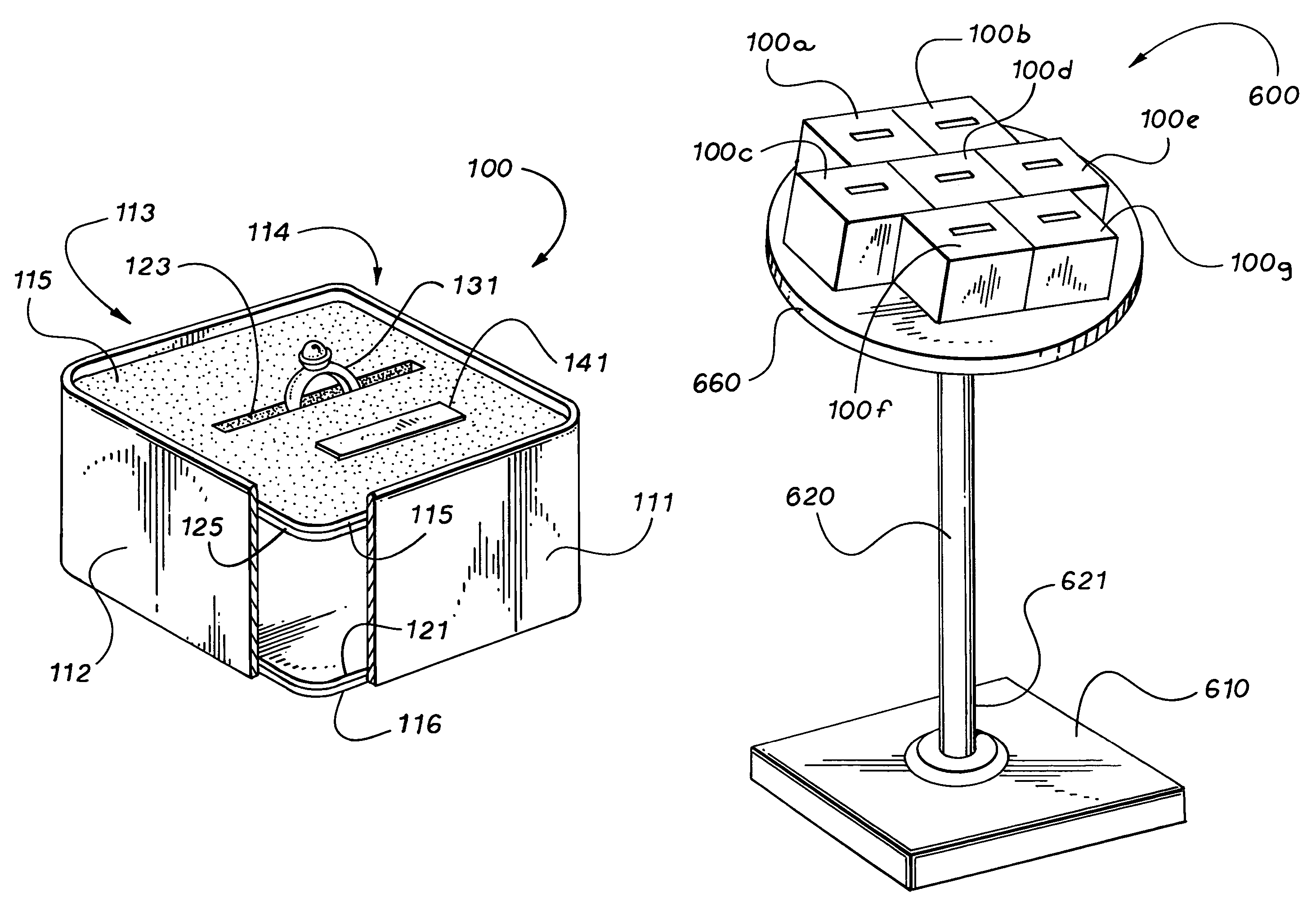
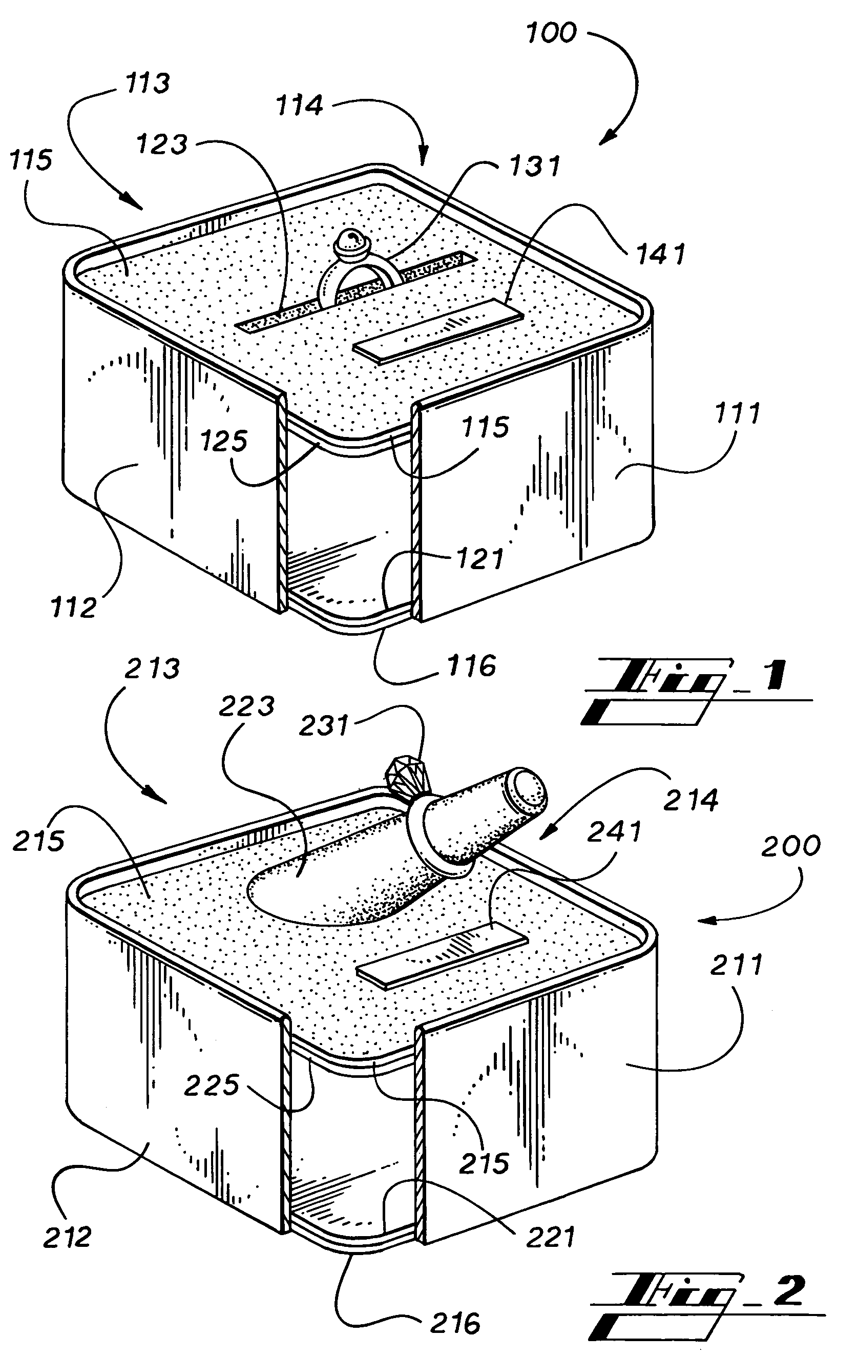
[0035]Referring now to FIG. 1, by way of example, and not limitation, there is illustrated a partial cut-away perspective view of article display unit 100. Preferably, article display unit 100 comprises sides 111, 112, 113, and 114, top 115, and bottom 116 arranged in a cube. Sides 111, 112, 113, and 114, top 115, and bottom 116 are preferably formed of a su...


PUM

PropertyMeasurementUnit
magnetic attraction forceaaaaaaaaaa
sizeaaaaaaaaaa
cylindrical shapeaaaaaaaaaa

Abstract

An article display and method of use thereof, comprising a magnetic article display for releasably attaching two or more jewelry displays together or to a platform, to provide an article display set, wherein any display can be easily separated from the article display set; thereby providing for individual viewing of the removed article display and / or rearrangement of the remaining article displays within the article display set.

Description

PRIORITY CLAIM TO RELATED US APPLICATIONS[0001]To the full extent permitted by law, the present non-provisional patent application is a continuation-in-part of and hereby incorporates by reference and claims priority to and the benefit of U.S. Non-Provisional patent application entitled “Article Display and Method of Use Thereof,” filed on Jan. 24, 2006, having assigned Ser. No. 11 / 337,991 now abandoned (which claims priority to Ser. Nos. 11 / 266,640, 11 / 252,534, 60 / 595,514, and 60 / 594,065); U.S. Non-Provisional patent application entitled “Slip Free Article Displays,” filed on Nov. 3, 2005, having assigned Ser. No. 11 / 266,640 (which claims priority to Ser. Nos. 11 / 252,534, 60 / 595,514, and 60 / 594,065); U.S. Non-Provisional patent application entitled “Slip Free Article Displays,” filed on Oct. 18, 2005, having assigned Ser. No. 11 / 252,534 (which claims priority to 60 / 595,514, and 60 / 594,065); U.S. Provisional patent application entitled “Separating Ring Tray Module,” filed on Jul. 12...

Claims


Application Information

Patent Timeline
Patent Type & Authority Patents(United States)
IPC IPC(8): A45C11/04
CPCA45C11/16Y10T29/53Y10S206/818A45C13/1069A47F5/04A47F7/022A47F7/024A47F7/03A47F2005/165
Inventor MOBLEY, TAMMY J.
Owner MOBLEY TAMMY J
Why Eureka
Try Eureka