
Plasma display panel (PDP)

a technology of display panel and plasma, which is applied in the direction of gas discharge electrodes, gas discharge vessels/containers, gas-filled discharge tubes, etc., can solve the problems of deteriorating luminance and light emission efficiency of pdp, weakened address discharge, etc., and achieves the effect of improving luminance and light emission efficiency, improving black region ratio, and improving bright room contras

Inactive Publication Date: 2010-07-20
SAMSUNG SDI CO LTD
View PDF22 Cites 0 Cited by
  • Summary
  • Abstract
  • Description
  • Claims
  • Application Information

AI Technical Summary

Benefits of technology

[0014]The present invention provides a Plasma Display Panel (PDP) that can improve a bright room contrast by increasing a black region ratio using a subtractive color effect without deteriorating luminance and light emission efficiency.
[0015]According to an embodiment of the present invention, a PDP includes: first and second substrates facing each other and spaced apart from each other; barrier ribs arranged between the first and second substrates and defining discharge cells; an address electrode extending in a first direction to correspond to the discharge cells; first and second electrodes arranged on one of the first and second substrates and extending in a second direction crossing the first direction to correspond to the discharge cells; a dielectric layer covering the first and second electrodes; a first colored layer arranged on a portion of the barrier ribs close to the first and second electrodes; and a second colored layer arranged on the dielectric layer and corresponding to the first colored layer, the first and second colored layers inducing a subtractive color effect.

Problems solved by technology

As a result, since the net space potential between the scan and address electrodes is lower than an initially supplied address voltage (Va), the address discharge is weakened and disappears.
However, the colored layer intercepts the visible light to deteriorate the luminance and light emission efficiency of the PDP.

Method used


Image

  • Plasma display panel (PDP)
  • Plasma display panel (PDP)
  • Plasma display panel (PDP)

Examples


Embodiment Construction

[0025]The present invention is described more fully below with reference to the accompanying drawings, in which embodiments of the present invention are shown. The present invention may, however, be embodied in many different forms and should not be construed as being limited to the embodiments set forth herein; rather these embodiments are provided so that this disclosure will be thorough and complete, and will fully convey the concept of the present invention to those skilled in the art. Wherever possible, the same reference numbers will be used throughout the drawings to refer to the same or like parts.

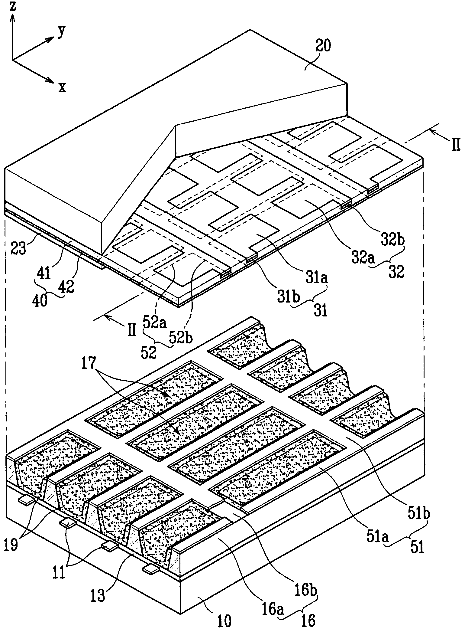
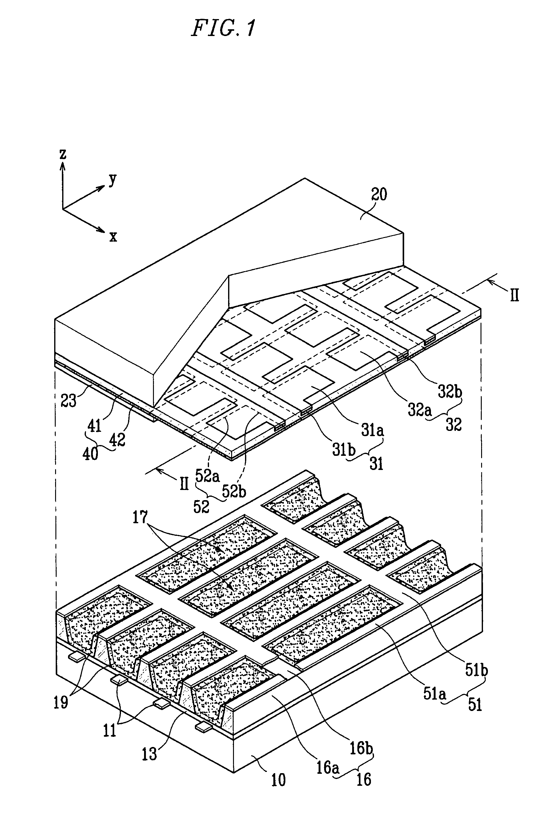
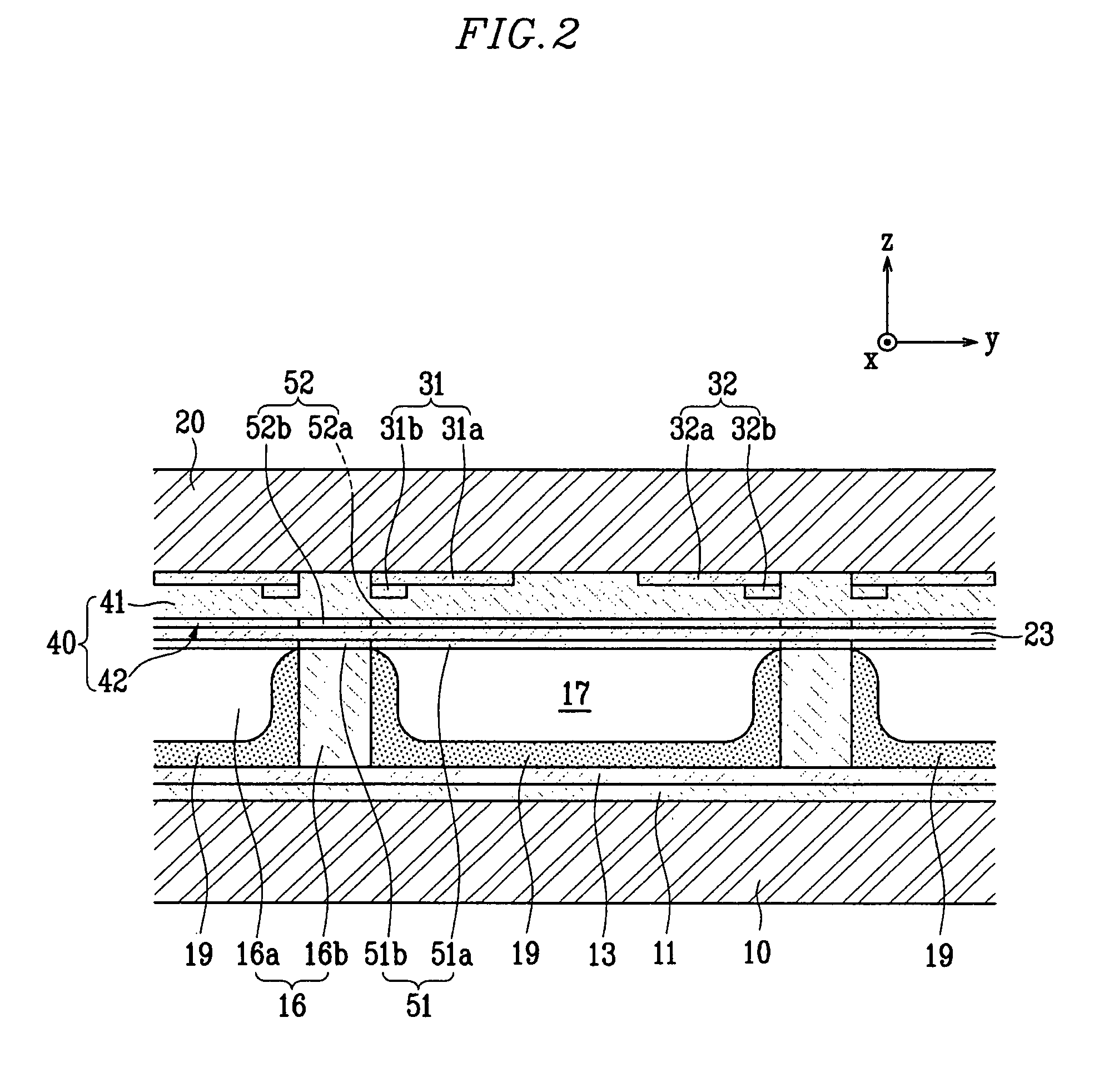
[0026]FIG. 1 is a schematic exploded perspective view of a Plasma Display Panel (PDP) according to a first embodiment of the present invention, and FIG. 2 is a sectional view taken along line II-II of FIG. 1.

[0027]Referring to FIGS. 1 and 2, a PDP according to a first embodiment of the present invention includes first and second substrates (hereinafter respectively referred to as “...


PUM


Abstract

A Plasma Display Panel (PDP) includes: first and second substrates facing each other and spaced apart from each other; barrier ribs arranged between the first and second substrates and defining discharge cells; an address electrode extending in a first direction to correspond to the discharge cells; first and second electrodes arranged on one of the first and second substrates and extending in a second direction crossing the first direction to correspond to the discharge cells; a dielectric layer covering the first and second electrodes; a first colored layer arranged on a portion of the barrier ribs close to the first and second electrodes, and a second colored layer arranged on the dielectric layer and corresponding to the first colored layer, the first and second colored layers inducing a subtractive color effect.

Description

CLAIM OF PRIORITY[0001]This application makes reference to, incorporates the same herein, and claims all benefits accruing under 35 U.S.C. §119 from an application for PLASMA DISPLAY PANEL earlier filed in the Korean Intellectual Property Office on the 29 day of Mar. 2006 and there duly assigned Serial No. 10-2006-0028285.BACKGROUND OF THE INVENTION[0002]1. Field of the Invention[0003]The present invention relates to a Plasma Display Panel (PDP), and more particularly, the present invention relates to a PDP that can improve a bright room contrast by increasing a black region ratio using a subtractive color effect while maintaining a high luminance and light emission efficiency.[0004]2. Description of the Related Art[0005]A Plasma Display Panel (PDP) is a display device that can display an image using red, green, and blue visible light created by exciting phosphors using Vacuum UltraViolet (VUV) rays emitted from a plasma created by a gas discharge.[0006]For example, in an Alternatin...

Claims


Application Information

Patent Timeline
Patent Type & Authority Patents(United States)
IPC IPC(8): H01J17/49
CPCH01J11/12H01J11/38H01J11/44H01J2211/444H01J11/24H01J2211/245
Inventor LEE, KYU-HANG
Owner SAMSUNG SDI CO LTD
Learn More