Combined ballast for fluorescent lamp and light emitting diode and method of driving same

a technology of fluorescent lamps and ballasts, which is applied in the direction of electric variable regulation, process and machine control, instruments, etc., can solve the problems of inability to include led and cfl driving circuits in the limited volume associated with the lamp assembly, add undesired cost and complexity to the lamp assembly, and achieve low cost and efficient integration of driver circuits

Inactive Publication Date: 2010-07-20
GENERAL ELECTRIC CO
View PDF13 Cites 6 Cited by
  • Summary
  • Abstract
  • Description
  • Claims
  • Application Information

AI Technical Summary

Benefits of technology

[0011]In another embodiment, a charge pump circuit is added to a conventional fluorescent lamp circuit. A soft-switching capacitor is included in the charge pump capacitor. The current that is supplied to the LED is determined by the value of the capacitor, the switching frequency, and the DC bus voltage, and thus provides for a delay in current supply to the LED. This delay advantageously protects the LED from the large voltage required to ignite the fluorescent lamp.
[0013]A primary benefit is the ability to efficiently integrate the driver circuits for the combined lamp assembly.
[0014]Another benefit relates to a low cost solution to the disparate needs of the different light sources.
[0015]Yet another benefit is associated with protecting the LED from the high voltage operatively associated with the fluorescent lamp driver circuit.
[0016]Still another benefit resides in the compact, low-power dissipating LED driver combined with the fluorescent lamp driver.
[0017]A further benefit results from ease of igniting the lamp since the circuit is not loaded during ignition.

Problems solved by technology

Thus, although combining the different types of light sources in a single lamp assembly is advantageous for light output, the combination presents unique issues since the needed driver circuits are so different.
As will be appreciated, separate driver circuits add undesired cost and complexity to the lamp assembly.
It is difficult to include separate LED and CFL driving circuits in the limited volume associated with the lamp assembly.
This solution is not as desirable since the LED and the fluorescent lamp are connected in series.
This voltage level is not desired for LEDs since it could potentially damage the LED light source.

Method used


Image

  • Combined ballast for fluorescent lamp and light emitting diode and method of driving same
  • Combined ballast for fluorescent lamp and light emitting diode and method of driving same
  • Combined ballast for fluorescent lamp and light emitting diode and method of driving same

Examples


Embodiment Construction

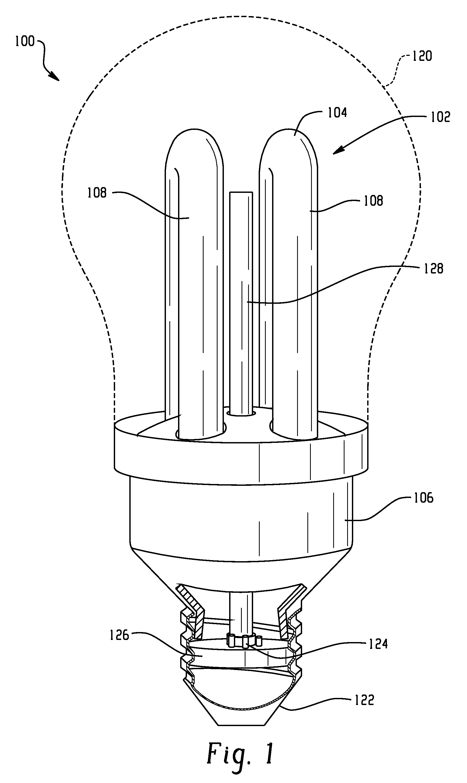
[0027]Turning first to FIG. 1, there is shown an LED integrated fluorescent lamp assembly 100 that has a low pressure fluorescent discharge lamp arrangement 102 that includes at least one low pressure discharge tube 104 attached to a housing or shell 106, typically formed from plastic. In the depicted embodiment, the fluorescent lamp or light source is a CFL lamp that includes two generally U-shaped low pressure discharge tubes 108, each discharge tube radiating white light (3000K-4000K, 480-1200 lm). Of course it will be appreciated that other fluorescent lamp arrangements could be used such as a helical discharge tube having an elongated path and in a manner that is generally well known in the art. The discharge tube arrangement 102 and shell 106 can be assembled together as a single element.

[0028]An envelope such as a glass envelope or outer bulb 120 may encompass the fluorescent discharge lamp arrangement 102. The outer envelope is secured to one end of the housing and the other...


PUM


Abstract

A circuit or combined ballast for driving a fluorescent lamp and at least one light emitting diode (LED) includes an integrated driver circuit having an alternating current (AC) circuit that includes at least one ballast coil for driving the fluorescent lamp and a direct current circuit for driving the LED having a secondary winding inductively coupled with the fluorescent lamp ballast coil for driving the LED. A method of driving a lamp assembly includes at least one fluorescent lamp and at least one light emitting diode (LED) and a combined driver circuit for supplying both the fluorescent lamp and the LED. The combined driver circuit supplies high voltage AC supply to a first portion of the driver circuit to the fluorescent lamp, supplies low voltage DC supply in a second portion of the driver circuit to the LED, and provides a secondary winding in the second portion of the driver circuit that is inductively coupled with a ballast coil in the first portion of the driver circuit that drives the fluorescent lamp.

Description

BACKGROUND[0001]This application relates to a lamp assembly, and more particularly a combined lamp assembly incorporating a fluorescent lamp and more preferably a compact fluorescent lamp (CFL) light source and at least one light emitting diode (LED) light source. More particularly, this application relates to a combined arrangement for operating the lamp assembly, and particularly a combined driver circuit for the two light sources. However, it will be appreciated that the disclosure may find use in related environments and applications.[0002]It is generally known to provide a lamp assembly having combined light sources. For example, different types of light sources may be combined in a lamp assembly where each light source provides a different type of light output, and the combined output provides a mixture of light that cannot be achieved by either light source on its own. Commonly owned and co-pending application (U.S. Ser. No. 12 / 021,880, filed 29 Jan. 2008) discloses a combine...

Claims


Application Information

Patent Timeline
Patent Type & Authority Patents(United States)
IPC IPC(8): H05B37/00H05B44/00
CPCH05B41/2827H05B35/00H01J61/327
Inventor MAROS, ISTVANBAKK, ISTVAN PETERNERONE, LOUIS R.CHEN, TIMOTHYKUMAR, NITIN
Owner GENERAL ELECTRIC CO
Why Eureka
Try Eureka