Multi-light driving device, LCD with multi-light driving device and method for driving LCD

a driving device and multi-light technology, applied in the direction of instruments, gas discharge lamp usage, climate sustainability, etc., can solve the problems of poor response time of moving picture images, persisting vision, image blurring, etc., to prevent flickering, easy adjustment, and prevent image blurring existing in the conventional lcd

Inactive Publication Date: 2010-07-20
GIGNO TECH CO LTD
View PDF5 Cites 0 Cited by
  • Summary
  • Abstract
  • Description
  • Claims
  • Application Information

AI Technical Summary

Benefits of technology

[0007]In view of the above-mentioned problems, an objective of the invention is to provide an LCD and a method for driving the same, which can eliminate the image blurring, prevent the flicker issue, and have satisfactory brightness of the LCD.
[0011]The LCD and the method for driving the same of the invention generate a dark zone to include a scan line being activated, which can simulate the impulse-type display and prevent the image blurring issue caused by the persistence of vision of human eyes. Furthermore, the LCD and the method for driving the same of the invention generate a dark zone having non-zero brightness, so that the brightness of the LCD screen would not be over decreased. In addition, since the dark zone has non-zero brightness, the brightness changing of the screen can be controlled within a proper range. Thus, the flicker issue can be prevented.
[0013]Since the multi-light driving device of the invention generates sets of digital switching signals using a digital-control method, which are phase controllable and duty cycle controllable, the relative brightness between a plurality of light-emitting units can be easily adjusted. Thus, a dark zone can be generated in the screen of the LCD by the brightness distribution of the light-emitting units. In other words, the multi-light driving device of the invention can generate a dark zone that includes a scan line, which is being activated. This can simulate the impulse-type display. Therefore, the image blurring issue existing in the conventional LCD can be prevented. Furthermore, since the brightness changing of the light-emitting units is controlled within a proper range when driven by the multi-light driving device, the flicker issue can be prevented.

Problems solved by technology

The LCD, however, has poor response time for the moving picture images, and, to make it worse, human eyes have the persistence of vision.
Therefore, some problems, such as image blurring, exist when using an LCD for the TV display.
Thus, the LCD is inferior to the conventional TV displays, which do not have the above-mentioned problem, and has limited applications for serving as a TV display.
In contrary, the conventional LCD utilizes hold-type display method to show images, such that when showing moving picture images, the image blurring caused by the persistence of vision will easily occur in the screen of the LCD.
Regarding the blink technology, since the light=emitting units perform on / off switching all the time, the brightness changing of the LCD screen is huge.
This may result in flicker issue of vision.
In addition, when the light-emitting units perform on / off switching all the time, the effective brightness of the whole screen is decreased and the quality of the display suffers.
When the current of the lamp passes through the transient, the current and the brightness of the lamp may not be accurately controlled, and thus the brightness uniformity between the lamps may not be easily maintained.

Method used


Image

  • Multi-light driving device, LCD with multi-light driving device and method for driving LCD
  • Multi-light driving device, LCD with multi-light driving device and method for driving LCD
  • Multi-light driving device, LCD with multi-light driving device and method for driving LCD

Examples


Embodiment Construction

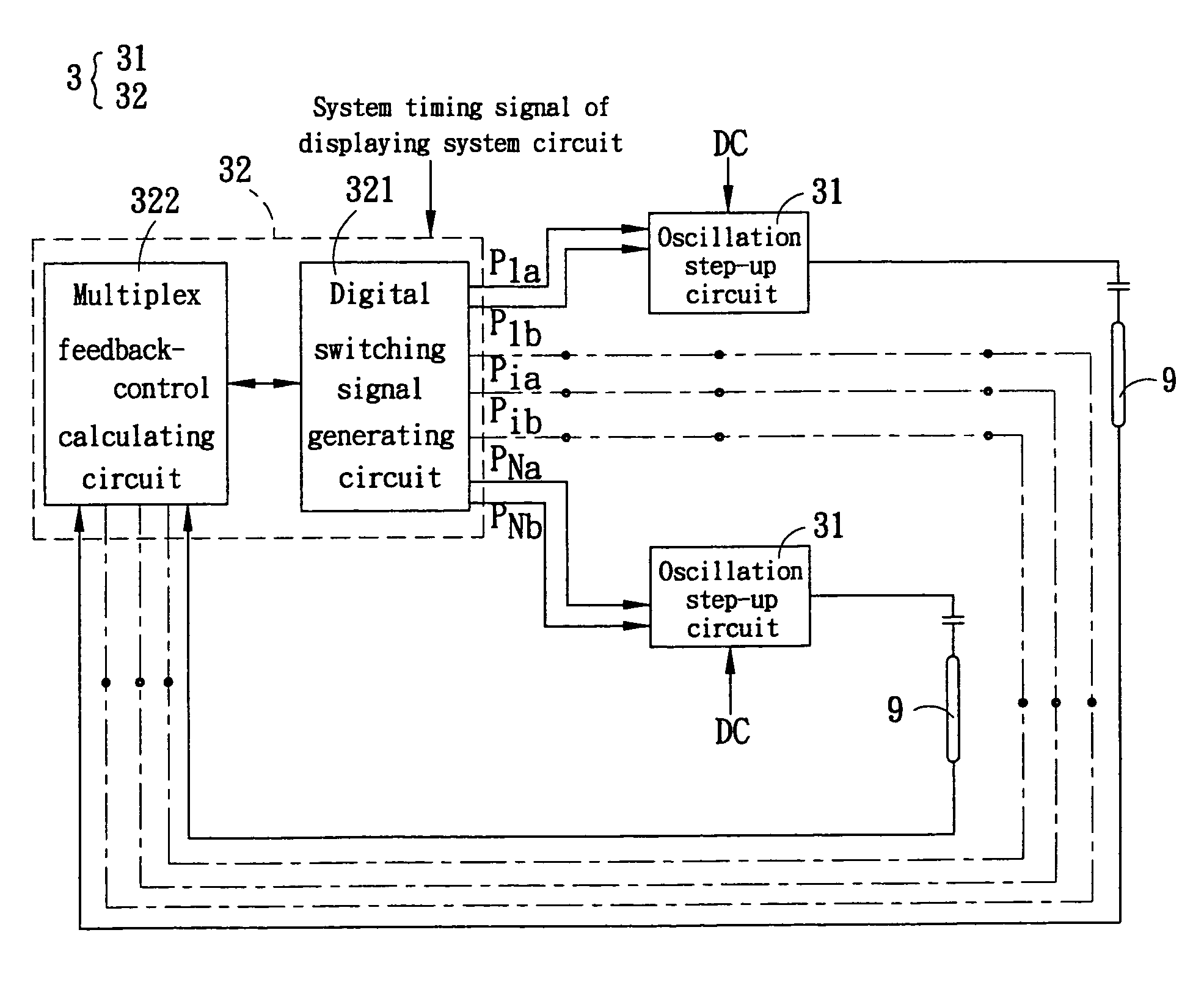
[0023]The method for driving an LCD according to the preferred embodiment of the invention will be described herein below with reference to the accompanying drawings. In the embodiment, the LCD includes a backlight module, a panel, and a multi-light driving device. The backlight includes a plurality of light-emitting units, each of which includes one or more lamps. The lamp can be a cold cathode fluorescent lamp (CCFL). The panel has a plurality of scan lines, and the LCD of the invention is a TFT-LCD with the backlight module being a direct back-light.

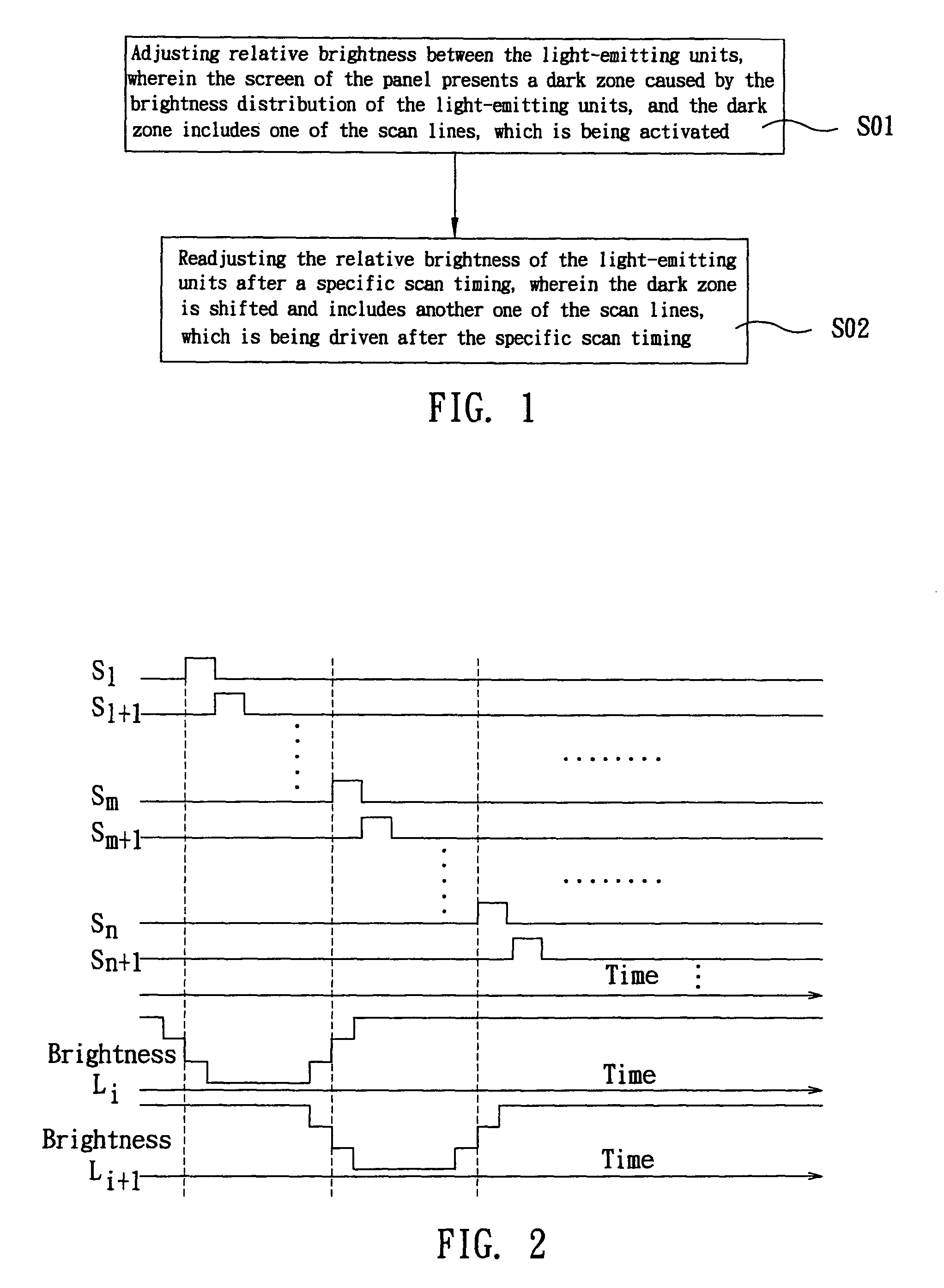
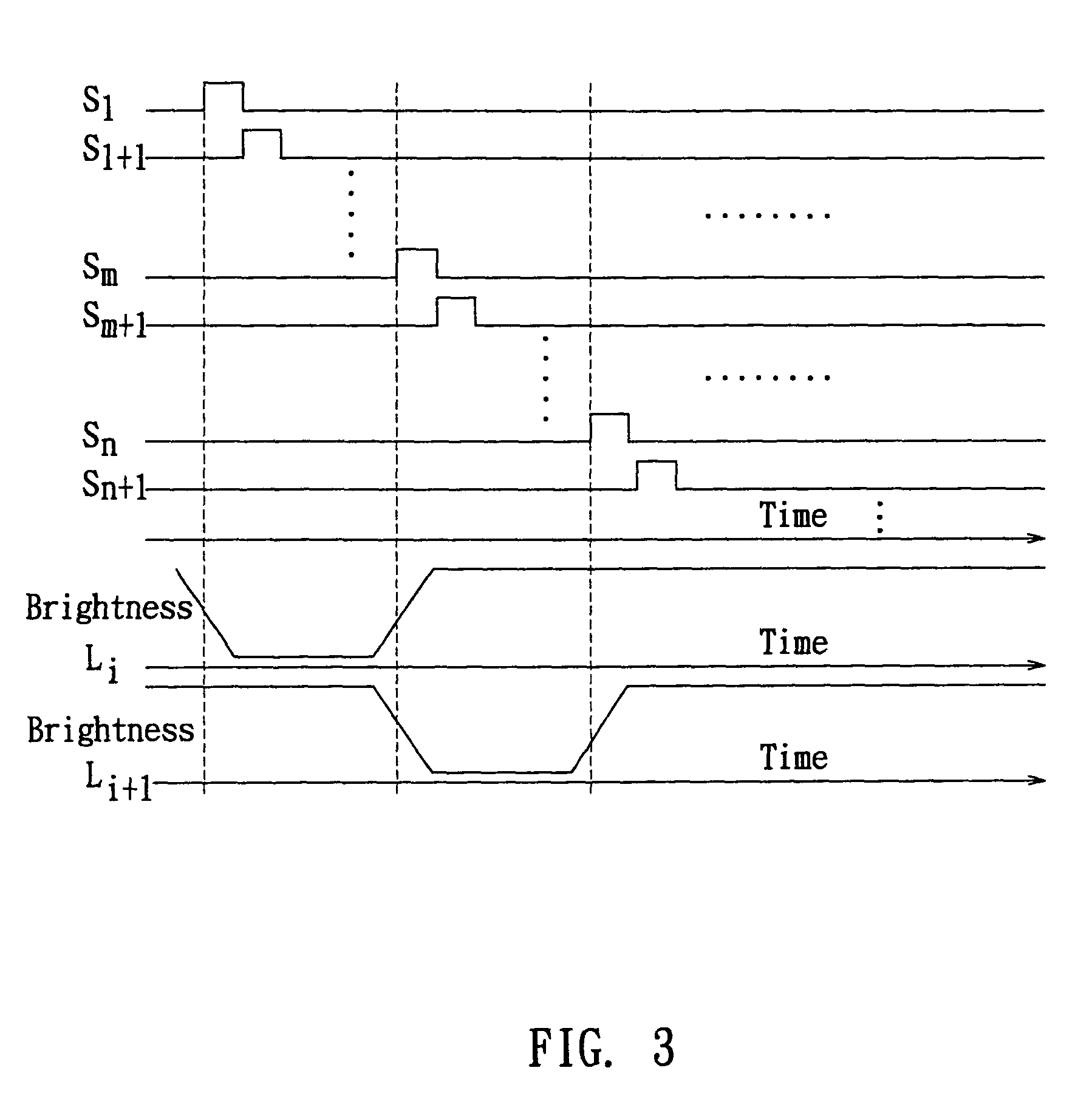
[0024]With reference to FIG. 1, the method for driving an LCD includes a first brightness adjusting step SO1 and a second brightness adjusting step S02.

[0025]In the first brightness adjusting step SO1, the relative brightness between the light-emitting units is adjusted by the multi-light driving device. Thus, the screen of the panel presents a dark zone caused by the brightness distribution of the light-emitting units, and the dark z...


PUM

PropertyMeasurementUnit
brightnessaaaaaaaaaa
phaseaaaaaaaaaa
currentaaaaaaaaaa

Abstract

A method for driving an LCD includes a first brightness adjusting step and a second brightness adjusting step. In the first brightness adjusting step, the relative brightness of a plurality of light-emitting units is adjusted, so that the screen of the LCD presents a dark zone. The dark zone is caused by the brightness distribution of the light-emitting units and includes a scan line being activated. In the second brightness adjusting step, the relative brightness of the light-emitting units is readjusted after a specific scan timing. Therefore, the dark zone is shifted such that another scan line, which is being activated, is located in the shifted dark zone. Furthermore, a multi-light driving device and an LCD with the multi-light driving device and driven by the method are disclosed.

Description

[0001]This application is a Divisional of co-pending application Ser. No. 10 / 715,475 filed on Nov. 19, 2003 now U.S. Pat. No. 7,218,307, and for which priority is claimed under 35 U.S.C. §120; and this application claims priority of Application No(s). 091218715 and 092101899 filed in Taiwan on Nov. 20, 2002 and Jan. 28, 2003, under 35 U.S.C. §119; the entire contents of all are hereby incorporated by reference.INVENTION[0002]The invention relates to a multi-light driving device, an LCD and a method for driving the LCD and, in particular, to a multi-light driving device, an LCD and a method for driving the LCD, which generate a dark zone that is shifted in sequence on a screen of the LCD.RELATED ART[0003]Liquid crystal displays (LCDs) are widely spread in electrical products such as computers. Accompanying the developing of LCD technology, the qualities of LCDs are improved and the screen sizes of LCDs are increased. Thus, the LCD is suitable for a TV display, which usually plays mov...

Claims


Application Information

Patent Timeline
Patent Type & Authority Patents(United States)
IPC IPC(8): G09G3/36G02F1/133G09G3/20G09G3/34H05B41/24H05B41/282
CPCG09G3/342H05B41/282G09G3/3611G09G2310/0237Y02B20/183Y02B20/00
Inventor CHAO, YUAN-JEN
Owner GIGNO TECH CO LTD
Why Eureka
Try Eureka