Steering switch for vehicle

a technology for steering switches and vehicles, applied in the direction of mechanical control devices, process and machine control, instruments, etc., can solve the problems of complicated wiring operation at the time of assembling the steering switch for a vehicle, limited mounting space for other switches, etc., and achieve the effect of convenient mounting to a casing

Inactive Publication Date: 2010-07-27
ALPS ALPINE CO LTD
View PDF21 Cites 6 Cited by
  • Summary
  • Abstract
  • Description
  • Claims
  • Application Information

AI Technical Summary

Benefits of technology

[0095]In a constitution like this, a switch that can change o...

Problems solved by technology

Accordingly, the dimension of the steering switch for a vehicle in the extension direction of the manipulating knob with respect to the support member is liable to become large and hence, there is possibility that the mounting space for other switches is limited.
Howev...

Method used


Image

  • Steering switch for vehicle
  • Steering switch for vehicle
  • Steering switch for vehicle

Examples


Embodiment Construction

[0109]Hereinafter, a steering switch for a vehicle of embodiments of the present invention is explained hereinafter.

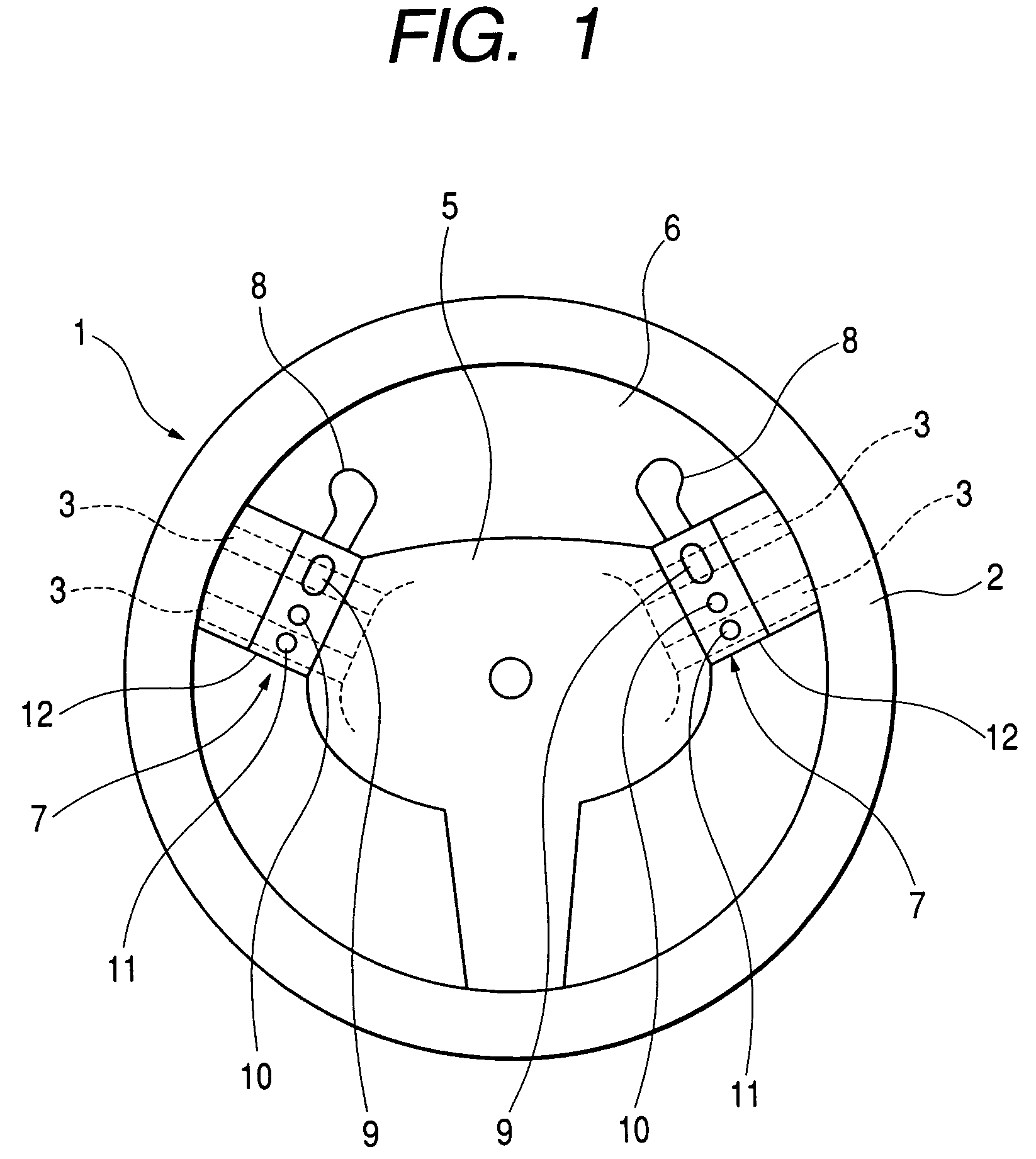
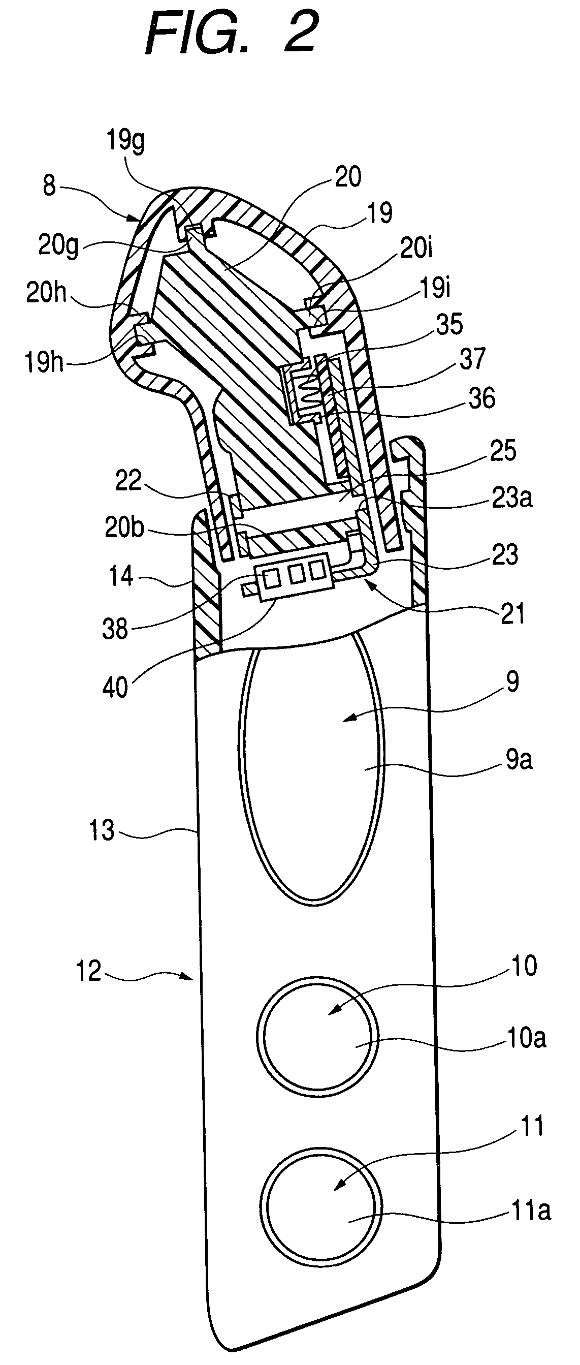
[0110]In the drawings, FIG. 1 is a front view showing a state in which an embodiment of a steering switch for a vehicle according to the first to the fifth inventions of the present invention is mounted on a steering wheel, FIG. 2 is a front view of the embodiment including a cross-section of the steering switch for a vehicle according to the first and the third inventions of the present invention, FIG. 3 is a left-side view of the embodiment including a cross-section of the steering switch for a vehicle according to the second and the fourth inventions of the present invention, FIG. 4 is an exploded perspective view of a rotary switch provided to the embodiment of the steering switch for a vehicle according to the first and the third inventions of the present invention, FIG. 5 is an exploded perspective view showing the positional relationship of a front-side casing m...


PUM


Abstract

Rotary support bodies which support both ends of a rod penetrating a manipulating knob body are formed by joining a first rotary support member which is arranged at one side of the manipulating knob body and supports one end of the rod and a second rotary support member which is arranged at another side of the manipulating knob body and supports another end of the rod, and one end of the rod is fixed to the second rotary support member, and another end of the rod is engaged with the first rotary support member. Accordingly, a manipulating knob can be mounted on a casing in a state the manipulating knob is mounted on the rotary support body.

Description

BACKGROUND OF THE INVENTION[0001]1. Field of the Invention[0002]The present invention relates to a steering switch for a vehicle which is mounted on a steering wheel of an automobile and is served for manipulating various equipment such as an automatic transmission.[0003]2. Description of the Related Art[0004]Conventionally, with respect to a steering wheel of an automobile, there has been known a steering wheel which mounts a plurality of steering switches at arbitrary positions. In this type of steering switch, in the midst of traveling in a drive range, an automatic transmission is manually shifted up by rotating a manipulating knob at a neutral position to a back-side from a front side of the steering wheel, while the automatic transmission is manually shifted down by rotating a manipulating knob at a neutral position to the front side from the back side of the steering wheel.[0005]As a conventional steering switch for a vehicle of this type, a steering switch for a vehicle disc...

Claims


Application Information

Patent Timeline
IPC IPC(8): B62D1/04G05G11/00G05G1/10G05G13/00B60K20/06B60Q1/00B60Q5/00F16H59/02
CPCB60K20/06B60Q1/0082B60Q5/003B62D1/046F16H59/02Y10T74/20256F16H2059/0239F16H2059/0247Y10T74/20834
Inventor TAKAHASHI, ATSUOYOKOYAMA, TATSUYA
Owner ALPS ALPINE CO LTD
Why Eureka
Try Eureka