
Riser pipe with auxiliary lines mounted on journals

a technology of auxiliary lines and riser pipes, which is applied in the direction of mechanical equipment, sealing/packing, and well accessories. it can solve the problems of reducing the longitudinal mechanical strength of the structure consisting of the entire riser, and reducing the longitudinal mechanical strength of the structur

Inactive Publication Date: 2010-07-27
INST FR DU PETROLE
View PDF35 Cites 26 Cited by
  • Summary
  • Abstract
  • Description
  • Claims
  • Application Information

AI Technical Summary

Benefits of technology

The invention is about a riser pipe section that includes a main tube, an auxiliary line element, and fastening means that join the main tube and auxiliary line element together. The fastening means allow for the transmission of longitudinal stresses and also allow for rotating motion between the auxiliary line element and the main tube. The main tube and auxiliary line element can be made of steel tubes reinforced with composite reinforcing strips made of materials like glass fibers, carbon fibers, or aramid fibers coated with a polymer matrix. The technical effect of this invention is to provide a more robust and flexible riser pipe section that can withstand higher levels of stress and has improved fatigue resistance.

Problems solved by technology

Owing to these elements mounted sliding into one another, the lines intended to allow high-pressure circulation of an effluent coming from the well or from the surface cannot take part in the longitudinal mechanical strength of the structure consisting of the entire riser.
Now, in the perspective of drilling at water depths that can reach 3500 m or more, the dead weight of the auxiliary lines becomes very penalizing.
One difficulty in making the riser according to document FR-2,799,789 lies in the fastening means for joining the auxiliary line length to the main tube.
As a result of the tensional stresses associated with the lever arm, the fastening means are subject to bending strains that may be harmful to the good working order of the riser.

Method used


Image

  • Riser pipe with auxiliary lines mounted on journals
  • Riser pipe with auxiliary lines mounted on journals
  • Riser pipe with auxiliary lines mounted on journals

Examples


Embodiment Construction

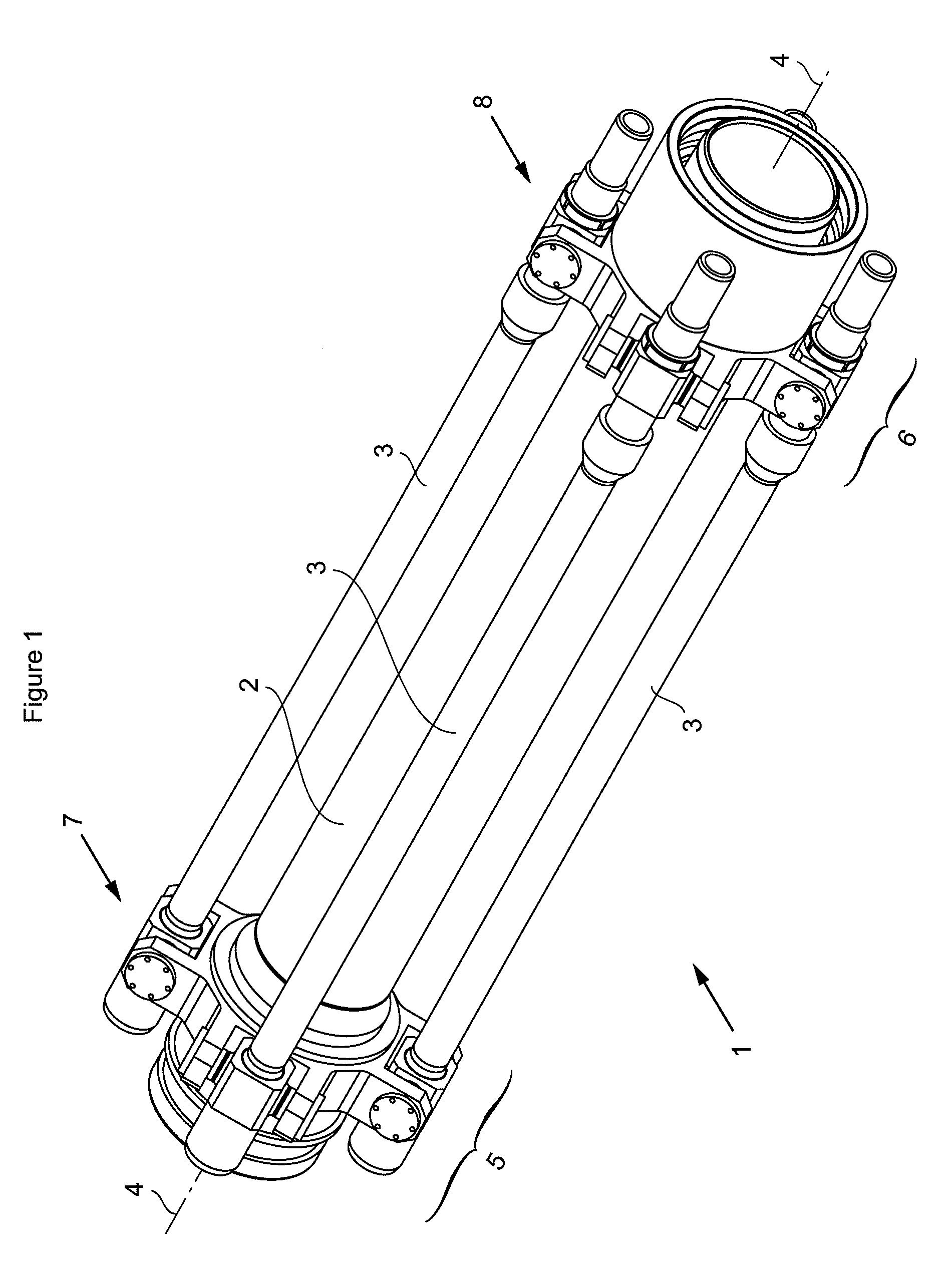
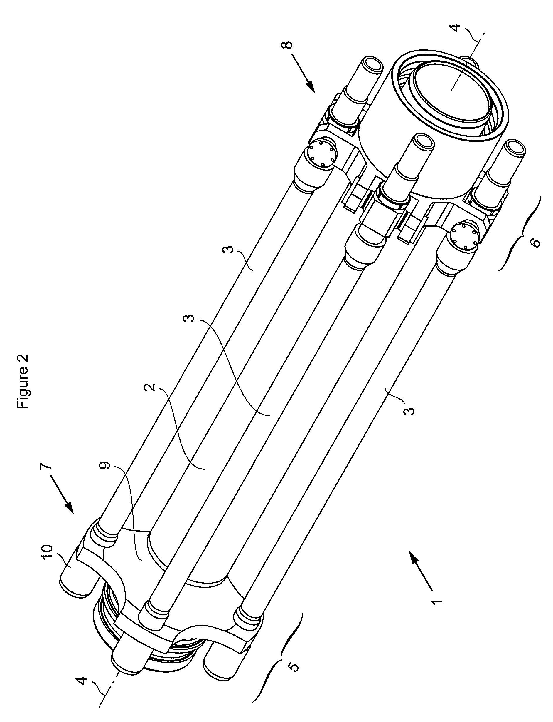
[0016]FIG. 1 shows a section 1 of a riser pipe. Section 1 is provided, at one end thereof, with female connecting means 5 and, at the other end, with male connecting means 6. To form a riser, several sections 1 are assembled end to end using connecting means 5 and 6.

[0017]Riser section 1 comprises a main tube element 2 whose axis 4 is the axis of the riser. The auxiliary lines or pipes are arranged parallel to axis 4 of the riser so as to be integrated in the main tube. Reference numbers 3 designate each of the auxiliary line elements. The length of elements 3 is substantially equal to the length of main tube element 2. At least one line 3 is arranged on the periphery of main tube 2. These lines, called kill line, choke line, are used to provide well safety during control procedures intended to check the inflow of fluids under pressure in the well. The booster line allows mud to be injected. The hydraulic line allows the blowout preventer, commonly referred to as B.O.P., to be contr...


PUM


Abstract

The invention relates to a riser pipe section comprising a main tube (2), at least one auxiliary line element (3) substantially parallel to said main tube (2) and at least two fastening means (7, 8) that connect the ends of said element (3) to main tube (2). The section is characterized in that fastening means (7, 8) allow longitudinal stresses to be transmitted from said element (3) to main tube (2) and in that at least one of fastening means (7, 8) allows at least a rotating motion of said element (3) in relation to said main tube (2), the rotating motion following an axis perpendicular to the plane passing through axis (4) of the main tube and through the axis of auxiliary line element (3).

Description

FIELD OF THE INVENTION[0001]The present invention relates to the field of very deep sea drilling and oil field development. It concerns a riser pipe element comprising at least one line, or auxiliary line, integrated in the main tube.BACKGROUND OF THE INVENTION[0002]A riser pipe is made up of an assembly of tubular elements whose length ranges between 15 and 25 m, assembled by connectors. These risers suspended in sea can be very heavy, which requires suspension means of very high capacity at the surface and suitable dimensions for the main tube and the linking subs.[0003]So far, the auxiliary lines: kill lines, choke lines, booster lines and hydraulic lines are arranged around the main tube and they comprise subs that fit together, fastened to the riser element connectors in such a way that these high-pressure lines can allow a longitudinal play between two successive line elements, without any disconnection possibility however. Owing to these elements mounted sliding into one anot...

Claims


Application Information

Patent Timeline
Patent Type & Authority Patents(United States)
IPC IPC(8): E21B29/12E21B7/12
CPCE21B17/085E21B17/1035E21B17/0853
Inventor PAPON, GERARDGUESNON, JEAN
Owner INST FR DU PETROLE
Learn More