Cable tie with oxygen sensor connector fastener

a technology of connector fasteners and oxygen sensors, applied in the field of oxygen sensor fasteners, can solve the problems of high resistance to rattling and highly undesirable, and achieve the effect of convenient use and inexpensive manufacturing

Active Publication Date: 2010-07-27
AVERY DENNISON CORP
View PDF49 Cites 39 Cited by
  • Summary
  • Abstract
  • Description
  • Claims
  • Application Information

AI Technical Summary

Benefits of technology

[0009]It is yet another object of the present invention to provide a cable tie of the type as described above which includes a limited number of parts, which is easy to use and which is inexpensive to manufacture.

Problems solved by technology

It has been found that, due to the substantial length of electrical cable 15, oxygen sensor 11 is rendered highly susceptible to rattling within the automobile body during operation of the car, which is highly undesirable.

Method used


Image

  • Cable tie with oxygen sensor connector fastener
  • Cable tie with oxygen sensor connector fastener
  • Cable tie with oxygen sensor connector fastener

Examples


Embodiment Construction

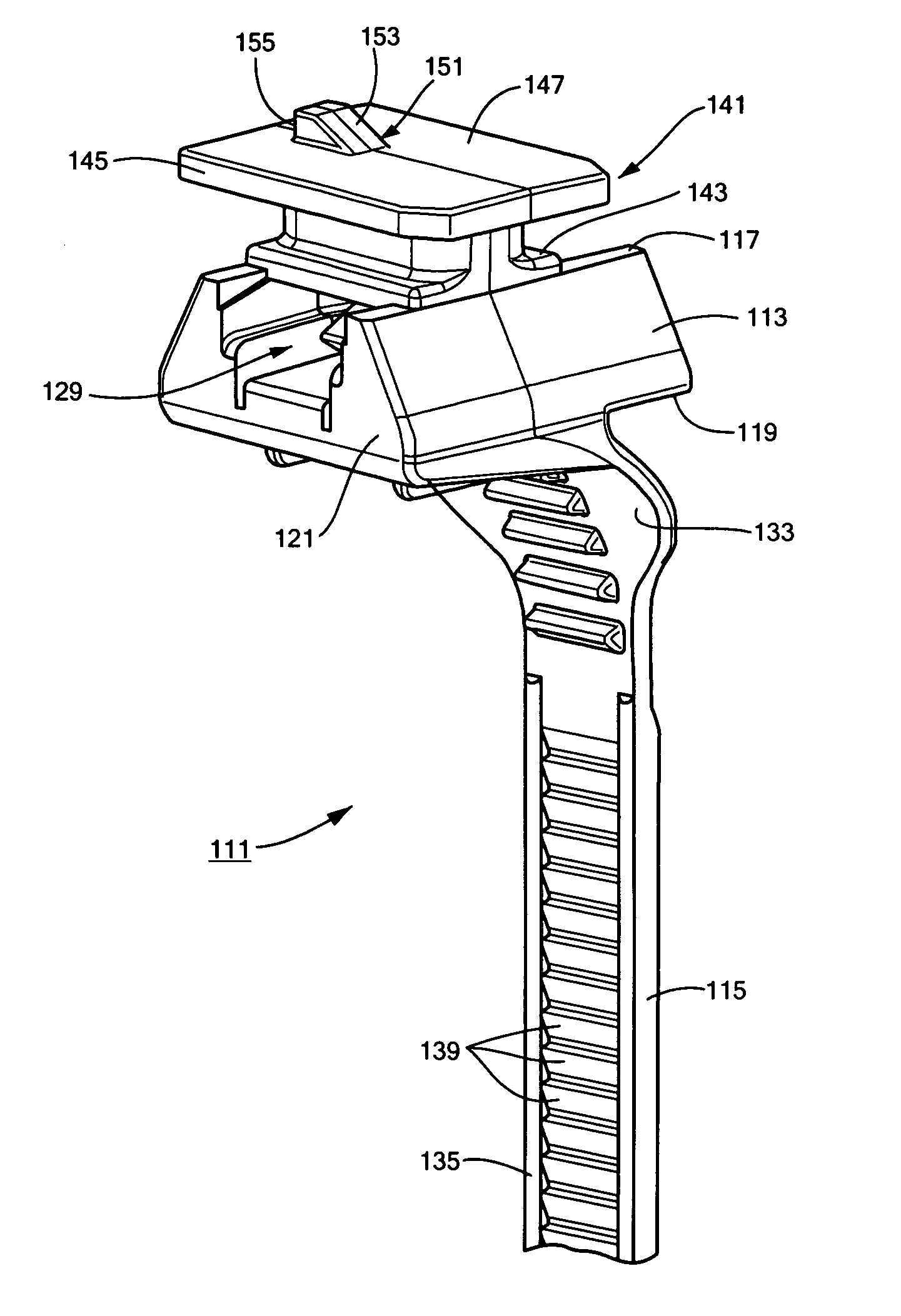
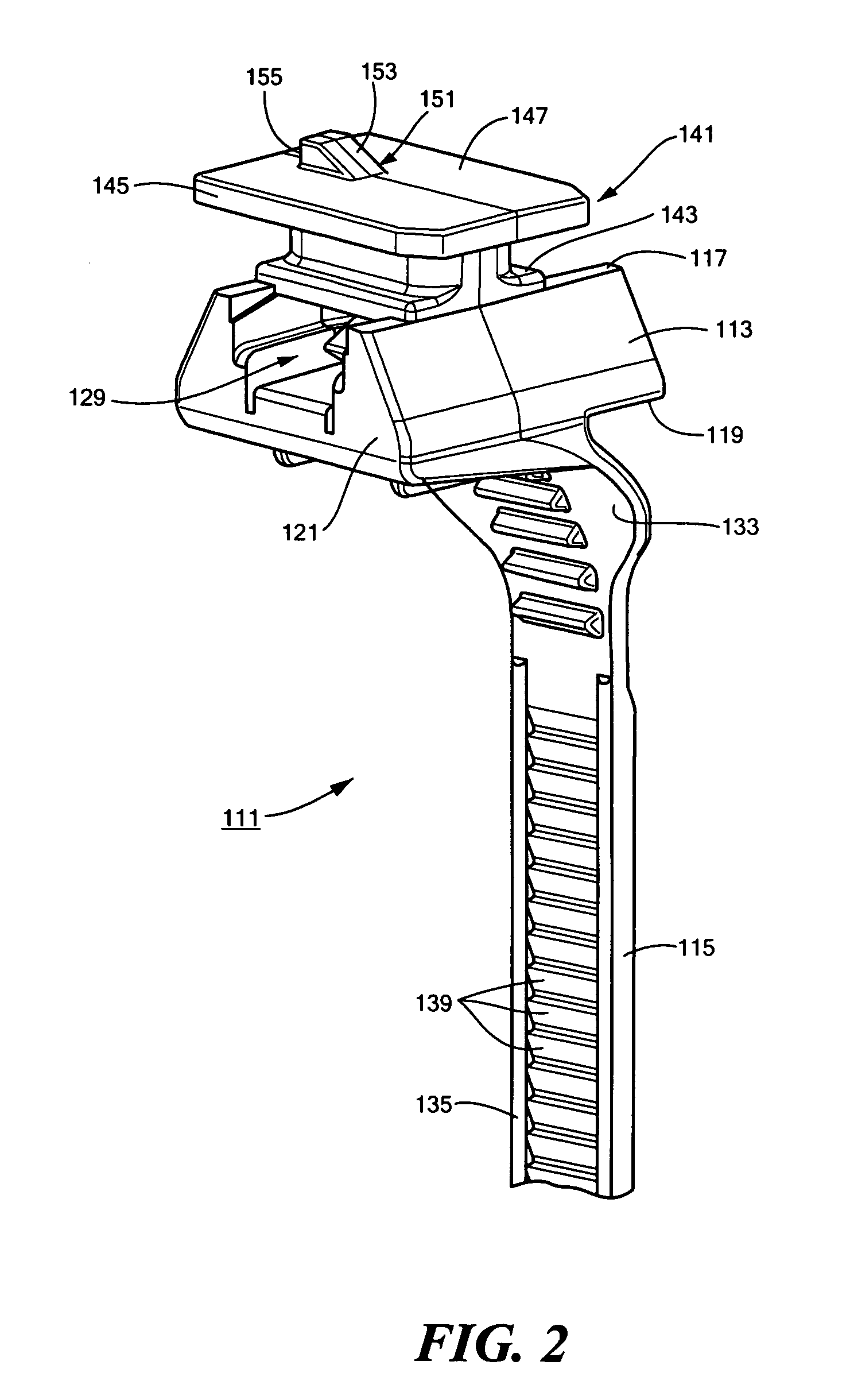
[0020]Referring now to FIGS. 2-4, there is shown a cable tie (also referred to herein simply as a tie) which is constructed according to the teachings of the present invention, the tie being identified generally as reference numeral 111. As will be described further in detail below, tie 111 is designed for connection with an electrical connector for an oxygen sensor for an automotive emissions control system. In turn, tie 111 can be used to retain the electrical connector against a wire harness for the automobile's electrical system.

[0021]Cable tie 111 comprises a locking head 113 and an attached strap 115. Preferably, tie 111 is manufactured of a plastic material, such as nylon, and is formed as a single piece using conventional molding techniques.

[0022]Locking head 113 is generally rectangular in shape and comprises an open top wall 117, a bottom wall 119, a front wall 121, a rear wall 123, a first side wall 125 and a second side wall 127. Together, top wall 117, bottom wall 119, ...


PUM


Abstract

A one-piece cable tie includes a locking head and an attached strap, the locking head being adapted to receive and selectively engage a portion of the strap when the tie is formed into a closed loop. The cable tie additionally includes a fastener formed onto the locking head that is designed for connection with the electrical connector for an oxygen sensor for an automotive emissions control system. The fastener includes a flattened platform that is spaced away from the top surface of the locking head by an inverted T-shaped standoff, the flattened platform being sized and shaped to be slidably disposed within a corresponding slot formed in the electrical connector. A ratchet tooth is formed onto the flat top surface of the platform and is shaped to engage the electrical connector in order to retain the fastener secured within the slot in the electrical connector.

Description

CROSS-REFERENCE TO RELATED APPLICATIONS[0001]The present application claims the benefit under 35 U.S.C. 119(e) of U.S. provisional Patent Application Ser. No. 60 / 673,238, filed Apr. 20, 2005, the disclosure of which is incorporated herein by reference.BACKGROUND OF THE INVENTION[0002]The present invention relates generally to the automotive industry and more particularly to oxygen sensors used in the automotive industry.[0003]Directives for monitoring the exhaust emissions of automotive vehicles have recently grown into prominence in an effort to minimize the pollutant effects that automobiles introduce into the environment (i.e., with respect to air quality). In particular, federal law currently mandates that all manufactured automobiles be equipped with an emissions control system which functions, among other things, to help an automotive engine (i) run as efficiently as possible and (ii) produce as few emissions as possible. One or more oxygen sensors are typically provided as pa...

Claims


Application Information

Patent Timeline
Patent Type & Authority Patents(United States)
IPC IPC(8): F16B15/00F16B45/00
CPCF16L3/233F16L3/2336F16L3/24Y10T24/141Y10T24/1498Y10T24/44026H02G3/32B60R16/0215F16L3/243
Inventor FRANKS, JOHN R.
Owner AVERY DENNISON CORP
Why Eureka
Try Eureka