Implant system with migration measurement capacity

a technology of implant system and measurement capacity, applied in the field of implant system, can solve the problems of human joints being damaged, articular cartilage covering the ends, and the implant of a prosthetic joint can become loose,

Active Publication Date: 2010-07-27
DEPUY PROD INC
View PDF13 Cites 109 Cited by
  • Summary
  • Abstract
  • Description
  • Claims
  • Application Information

AI Technical Summary

Problems solved by technology

Human joints can become damaged as a result of accident or illness.
Such damage can be, for example, to the articular cartilage covering the ends of the bones at the joint as well as the intra-articular cartilage between the ends of the adjacent bones of the joint.
Even with the use of bone cement and porous surfaces, it is possible for a prosthetic joint implant to become loose over time.
Loose bone-contacting components of a joint prosthesis (for example, stems received in the intramedullary canal) can become painful for the patient, and such loosening can eventually require revision surgery.
However, accurate measurement of movement of bone-contacting prosthetic joint components can be problematic.
Standard radiographs taken at different times (for example, immediately post-surgery and several months post-surgery) can be compared, but it would be difficult to detect small movements of the joint components accurately.
More sophisticated techniques can also be used, but can be costly and can require special equipment.
For example, radiostereometry analysis could be used, but this method requires that tantalum beads be implanted and requires software and expertise to obtain an accurate measurement of implant movement.
In addition, the more sophisticated measurement techniques may expose the patient to additional radiation.

Method used


Image

  • Implant system with migration measurement capacity
  • Implant system with migration measurement capacity
  • Implant system with migration measurement capacity

Examples


Embodiment Construction

[0030]Embodiments of the present invention and the advantages thereof are best understood by referring to the following description and drawings, wherein like numerals are used for like and corresponding parts of the drawings.

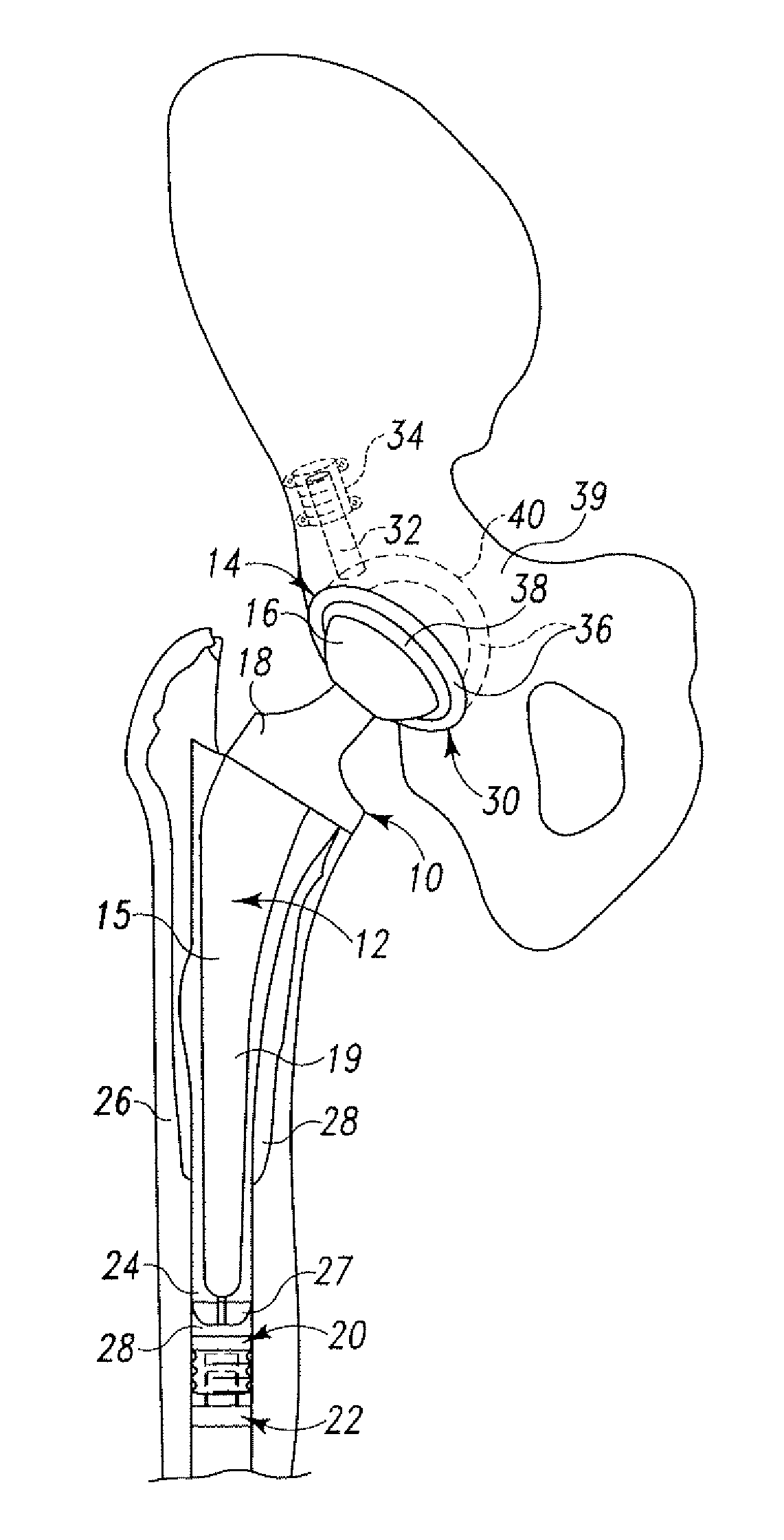
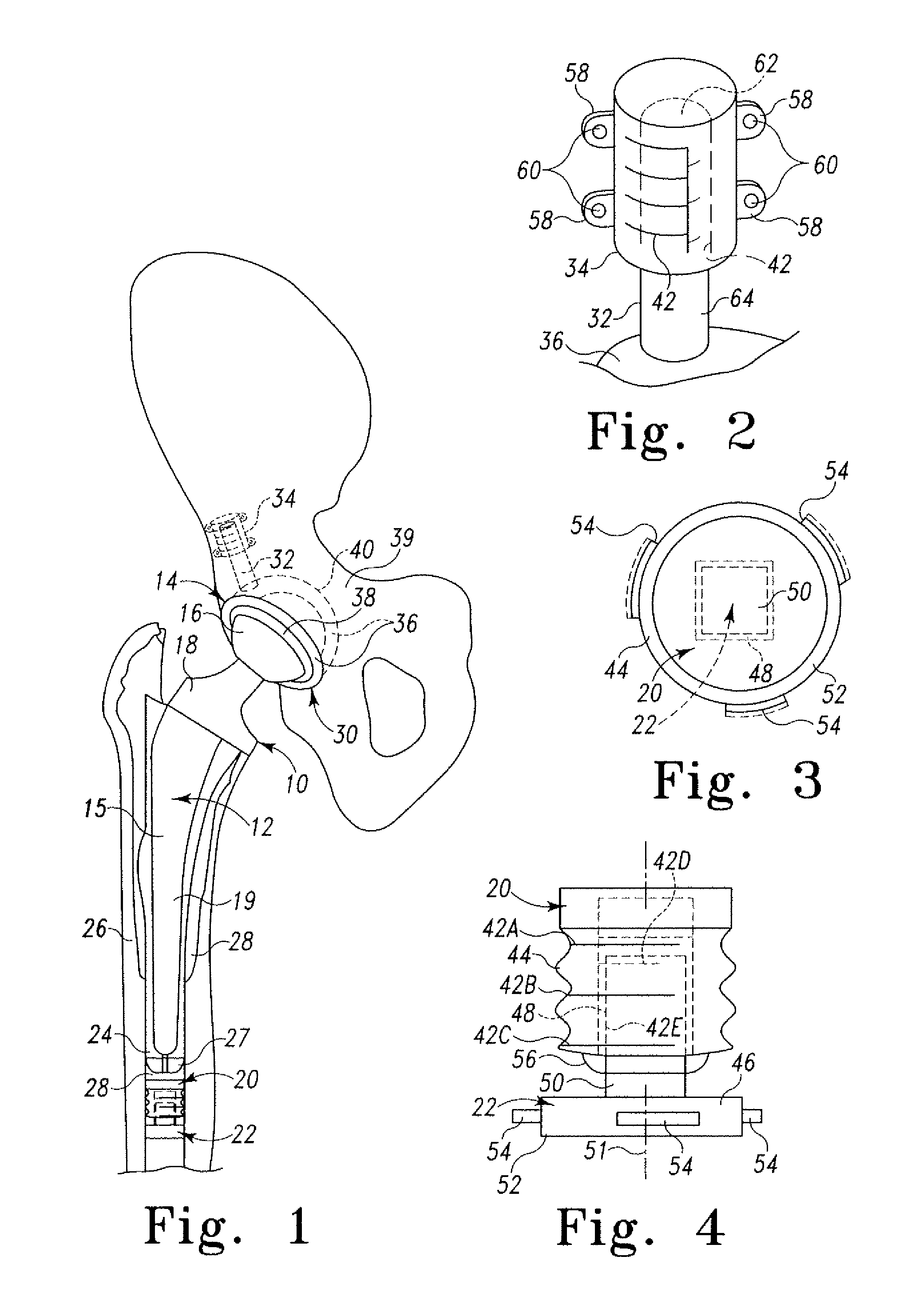
[0031]A first embodiment of an orthopaedic implant system illustrating the principles of the present invention is illustrated in FIGS. 1-4. The first illustrated joint implant system 10 comprises a prosthetic hip joint. The illustrated prosthetic hip joint includes a proximal femoral system 12 and an acetabular system 14.

[0032]The first illustrated proximal femoral system 12 includes a proximal femoral implant component 15. The proximal femoral implant component 15 includes a femoral head 16 and a femoral stem 18. The femoral head 16 comprises an articulating portion of the proximal femoral implant component 15 and the femoral stem 18 comprises a fixation portion 19. The femoral head 16 is substantially spherical and is assembled with the femoral stem 18 in a s...


PUM


Abstract

Position reference members are provided as part of an orthopaedic implant system. Both position reference members can be implanted on or in the same bone as the other parts of the implant. One of the position reference members is fixed to the bone and the other position reference member is movable with another part of the implant, such as a stem received in the intramedullary canal. The movable position reference member can move with respect to the fixed position reference member. At least one of the position reference members includes indicia such as a main scale or a vernier scale. Parts of the indicia and position reference members are radio-opaque and parts are radiolucent. Post-operative changes in the relative positions of the position reference members can be measured by radiography or fluoroscopy so that changes in the implant position can be monitored over time.

Description

TECHNICAL FIELD OF THE INVENTION[0001]The present invention relates to implant systems for use in treating the skeletal systems of human patients, and more particularly, to prosthetic joints used in replacing parts of human joints, such as the hip, knee, shoulder, ankle and elbow.BACKGROUND OF THE INVENTION[0002]Human joints can become damaged as a result of accident or illness. Such damage can be, for example, to the articular cartilage covering the ends of the bones at the joint as well as the intra-articular cartilage between the ends of the adjacent bones of the joint. When the damage to the joint is severe, a prosthetic joint can be implanted to improve the comfort and mobility of the patient.[0003]Prosthetic joints have been developed to replace native tissue of several human joints. There are a variety of knee prostheses, hip prostheses, shoulder prostheses, ankle prostheses, elbow prostheses and wrist prostheses available to relieve patient suffering. Such devices are availa...

Claims


Application Information

Patent Timeline
Patent Type & Authority Patents(United States)
IPC IPC(8): A61B17/58A61B17/74A61B19/00A61F2/00A61F2/30A61F2/32A61F2/34A61F2/36A61F2/38A61F2/40A61F2/42A61F2/46
CPCA61F2/30723A61F2/30724A61F2/4657A61B17/742A61B2019/461A61B2019/467A61F2/30767A61F2/32A61F2/34A61F2/36A61F2/3662A61F2/3676A61F2/38A61F2/40A61F2/4202A61F2/4261A61F2002/30056A61F2002/3008A61F2002/30093A61F2002/30224A61F2002/30235A61F2002/30331A61F2002/30332A61F2002/30481A61F2002/3055A61F2002/30578A61F2002/30579A61F2002/30601A61F2002/30606A61F2002/30616A61F2002/30617A61F2002/30726A61F2002/30769A61F2002/30878A61F2002/30925A61F2002/3611A61F2002/3625A61F2002/4205A61F2002/4631A61F2002/4658A61F2002/4668A61F2210/0019A61F2220/0025A61F2220/0033A61F2230/0069A61F2250/0032A61F2250/0097A61F2250/0098A61F2310/00017A61F2310/00023A61F2310/00029A61F2310/00113A61F2310/00131A61F2310/00179A61F2002/30092A61B2090/061A61B2090/067
Inventor SOUTHWORTH, CARLETON B.
Owner DEPUY PROD INC
Why Eureka
Try Eureka