Flicker correction method and device, and imaging device

a technology which is applied in the field of flicker correction and image pickup devices, can solve the problems of unavoidable flicker, and achieve the effect of flicker correction and flicker correction flexibly

Inactive Publication Date: 2010-07-27
SONY CORP
View PDF20 Cites 30 Cited by
  • Summary
  • Abstract
  • Description
  • Claims
  • Application Information

AI Technical Summary

Benefits of technology

[0013]It is therefore desirable to overcome the above-mentioned drawbacks of the related art by providing a flicker correction method and apparatus and an image pickup device, in which flicker can flexibly be corrected even when the light intensity of a light source varies.
[0029]Therefore, according to the present invention, even when the light intensity of the light source varies, the flicker correction can thus be made flexibly.

Problems solved by technology

The flicker is a problem unavoidably taking place when an object is imaged with a digital camera using an image sensor to image the object under the light of a flickering light source with the timing of charge storage being shifted.

Method used


Image

  • Flicker correction method and device, and imaging device
  • Flicker correction method and device, and imaging device
  • Flicker correction method and device, and imaging device

Examples


Embodiment Construction

[0041]The present invention will be described in detail below concerning the embodiments thereon with reference to the accompanying drawings. It should be noted that the present invention is not limited to the embodiments which will be described herebelow but it may be can be modified in various manners, constructed alternatively or embodied in various other forms without departing from the scope and spirit thereof.

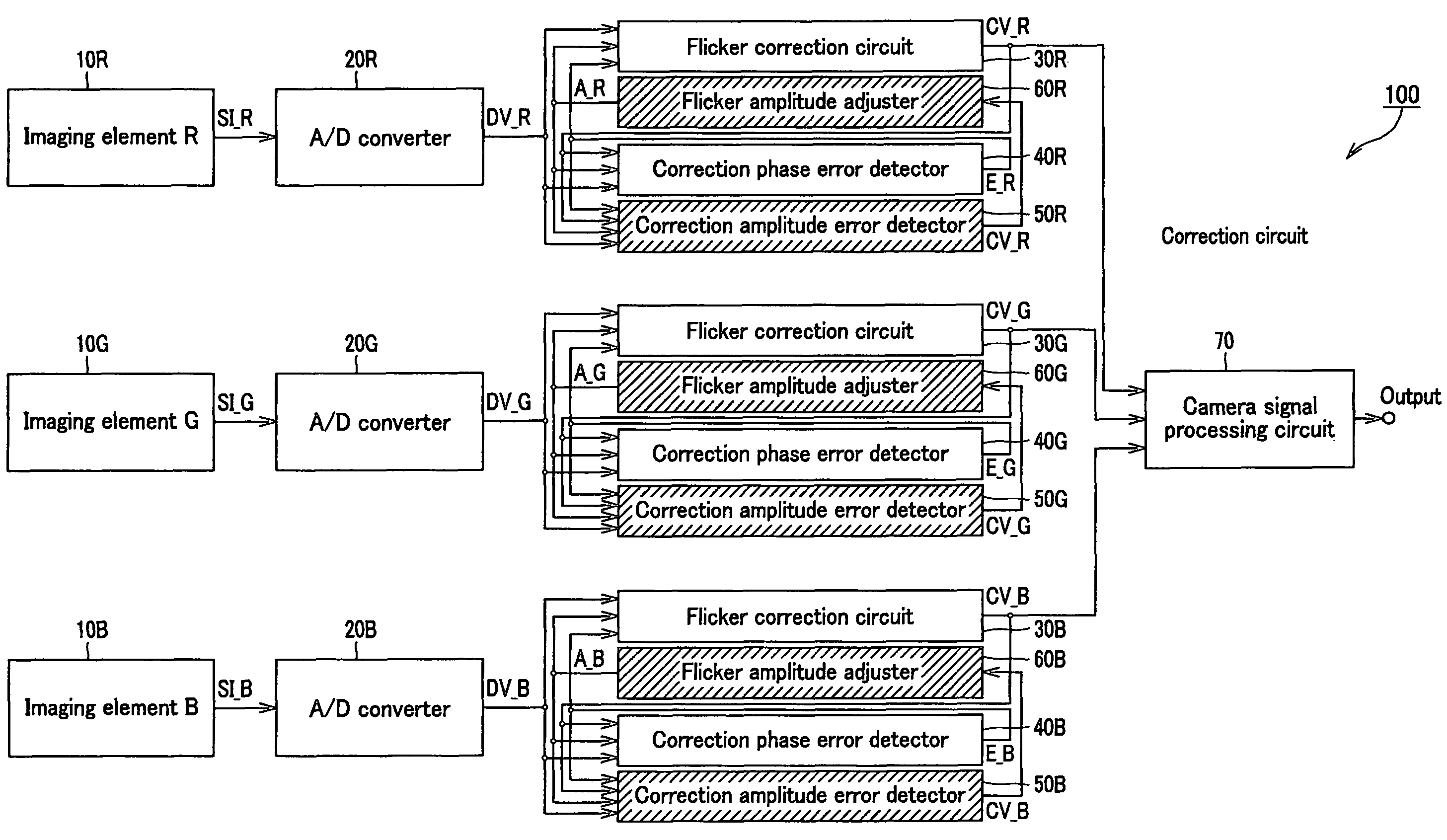
[0042]The present invention is applicable to an image pickup device constructed as shown in FIG. 5. The image pickup device is generally indicated with a reference numeral 100.

[0043]The image pickup device 100 includes a red color image sensing device (image element) 10R, green color image sensing device (imaging element) 10G, blue color image sensing device (imaging element) 10B, A-D converters 20R, 20G and 20B to digitize image signals SI_R, SI_G and SI_B of color images captured by the image sensing devices 10R, 10G and 10B, respectively, flicker correction circuits 30...


PUM


Abstract

Even when the light intensity of the light source varies, the flicker correction can thus be made flexibly. The present invention provides a flicker correction method comprising the steps of predicting, from an image of a present flicker-corrected frame, a flicker of an image of a next frame to generate two types of flicker images having flickers different in level from each other added thereto, detecting a flicker component through comparison between the generated two types of flicker images and an image of an input next frame, generating a flicker correction value on the basis of the detected flicker component, and making flicker correction by adding the generated flicker correction value to an input image frame by frame.

Description

CROSS REFERENCES TO RELATED APPLICATIONS[0001]The present invention contains subject matter related to Japanese Patent Application JP 2005-141614 filed in the Japanese Patent Office on May 13, 2005, the entire content of which is incorporated herein by reference.BACKGROUND OF THE INVENTION[0002]1. Field of the Invention[0003]The present invention relates to a flicker correction method and device, and an image pickup device, in which a flicker is corrected by subtracting a flicker correction signal from an image signal.[0004]2. Description of the Related Art[0005]In the conventional image sensor, the timing of charge storage differs depending upon whether the charge storage is made per plane or per line. Generally, timing of the charge storage per plane is called “global shutter system” while timing of the charge storage per line is called “rolling shutter system”. Most of the CCDs have adopted an image sensor of the global shutter type in the past. Recently, however, increasingly mo...

Claims


Application Information

Patent Timeline
Patent Type & Authority Patents(United States)
IPC IPC(8): H04N9/73H04N5/235H04N5/243
CPCH04N5/235H04N5/2357H04N23/70H04N23/745H04N23/00H04N25/60
Inventor ONO, NORIYUKINAKASUJI, MOTOHIRONISHIDE, YOSHIAKIIKEYAMA, HIROMASA
Owner SONY CORP
Why Eureka
Try Eureka