Adjustable hydrocephalus valve

a technology of hydrocephalus and valve body, which is applied in the direction of wound drains, catheters, intravenous devices, etc., can solve the problems of unfavorable sliding characteristics between silicon and the rotor, unsatisfactory solutions have not yet been achieved with the valves of the prior art, and achieve strong self-locking action

Active Publication Date: 2010-08-03
CHRISTOPH MIETHKE
View PDF16 Cites 39 Cited by
  • Summary
  • Abstract
  • Description
  • Claims
  • Application Information

AI Technical Summary

Benefits of technology

[0022]The object of at least one possible embodiment is to eliminate or virtually eliminate these disadvantages of the adjustable valves of the prior art. The application teaches that this object can be achieved with at least one possible embodiment disclosed herein. The particular object of the application is to make a valve adjustment possible only when the patient is in the standing position or in partly diagonal positions, which valve adjustment has no influence on the setting when the patient is in the reclining position.SUMMARY

Problems solved by technology

The valves of the prior art help considerably, of course, but a satisfactory solution has not yet been achieved with the valves of the prior art.
The function of a construction of this type is somewhat doubtful, however, because in actual use, the housing is carrying a flow of a watery solution (liquor).
The sliding characteristics between silicon and the rotor are thereby unfavorably altered.
The elastic tension is insufficient to guarantee a friction-tight protection against twisting.
Since it is practically impossible for a modern human being to avoid contact with such things, proposed solutions of this type are simply impractical.
This principle has in fact shown itself to be susceptible to failure in actual practice.
Although unintentional rotation is prevented, the intended adjustment is frequently unsuccessful.
This problem can be traced to the difficulty of reliably determining the exact position of the valve, because in actual use, friction forces that are difficult to calculate interfere with or even totally prevent the movement of the sliding magnets inside the valve.
An additional disadvantage is that because the layers of skin at these points can be rather thick, the two sliding magnets must be pulled far apart, whereby the forces resulting from the externally applied magnetic field become exponentially smaller as the distance increases, and in any case are then no longer sufficient to pull the magnets apart.
Here, too, the extremely problematic technology of a 100% magnetic brake in a hydrocephalus valve also becomes apparent.
This principle has never been found to be either practical or reliable.
In particular, the many small moving parts contribute to a critical addition of disruptive friction forces, which cannot be controlled, for among other reasons on account of the small size of the valve and also as a result of the magnets used.
The pins can very easily tip out of alignment, and the friction in the threads that is applied externally with a long lever arm is almost impossible to overcome with the very weak magnetic field derived from the small magnets.
The thread must also have some play to allow smooth movement, which in turn is disadvantageous to the accuracy of the adjustment.
The location of the valve is also problematic here, and an exact adjustment is practically impossible to achieve on account of the small size of the parts that have to be moved.
Because of the use of a silicone membrane, the reproducible setting of the opening pressure is impossible, because the properties of the material vary incalculably.
For the reasons indicated above, this design has not yet reached a stage where it is ready for the market.
However, clinical use has made it clear that the pin can cause a critical jamming of the rotor.
The manufacturer was forced to withdraw this unreliable technology from the market and thereafter market the valve without the mechanism to prevent the unintentional adjustment.
The danger of the unintentional adjustment therefore remains present, in particular when the requirement for the ability to reliably adjust the valve is taken into consideration.
An additional disadvantage of the system of the prior art is that the adjustment must be effective both in the standing position as well as in the reclining position.
However, this is a characteristic that is frequently undesirable.
The consequence for the patient is a physiologically uncomfortable pressurization of the ventricle of the brain immediately after standing up, which can lead to discomfort and dizziness as well as to serious complications such as subdural effusions and bleeding that must be treated by surgery.
It is not possible to prevent such complications with the valves described above.
In this case, the adjustment travel that is converted into a variation of the spring load is particularly large.

Method used


Image

  • Adjustable hydrocephalus valve
  • Adjustable hydrocephalus valve
  • Adjustable hydrocephalus valve

Examples


Embodiment Construction

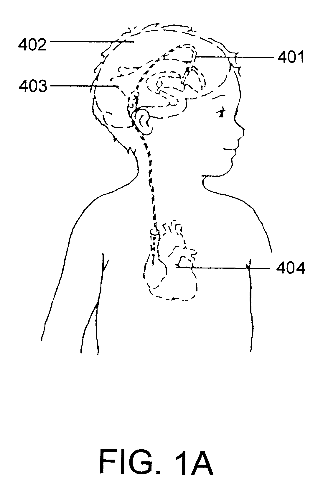
[0081]FIG. 5 shows an example of a hydrocephalus treatment device connected to a patient. The device comprises a ventriculo-atrial (VA) shunt 401. The VA shunt 401 moves cerebrospinal fluid from the ventricles 403, or spaces in the brain 402, into the atrium, or top chamber, of the heart 404 through a vein in the neck.

[0082]FIG. 7 shows an example of a hydrocephalus treatment device connected to a patient. The device comprises a ventriculo-peritoneal (VP) shunt 406. The VP shunt moves cerebrospinal fluid from the ventricles 403, or spaces in the brain 402, to a space in the peritoneal cavity inside the abdominal cavity 405.

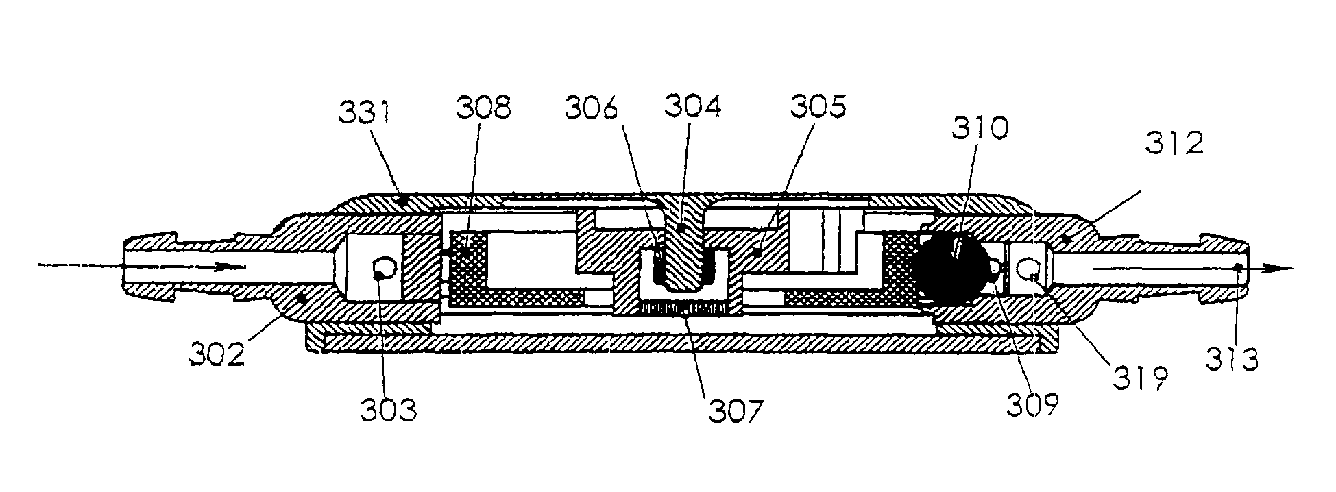
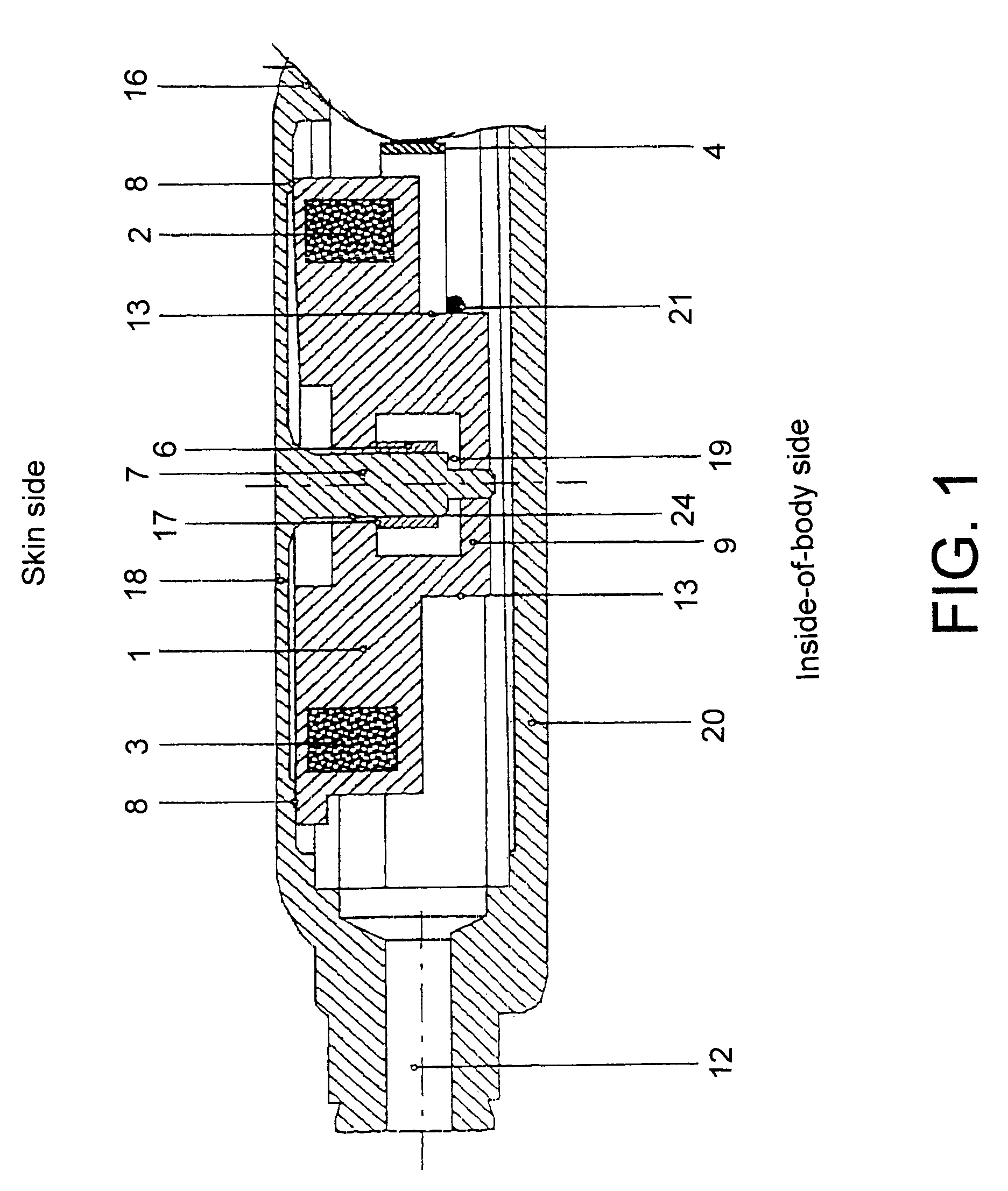
[0083]In the accompanying drawings, FIGS. 10, 11 and 12 illustrate one exemplary embodiment.

[0084]The valve comprises a solid metal housing 330. In the exemplary embodiment, the valve also includes a valve ball 310 as the closing part of the valve, a gravitation part 308 to produce an elevated closing pressure in the valve, a spring system 316 with an adjustment d...


PUM


Abstract

Hydrocephalus valves, the valve pressure of which, when the patient is in the standing position, is determined at least partly by the weight of an additional gravitation part, are provided with an adjustable spring which partly or fully neutralizes the action of the weight. The abstract of the disclosure is submitted herewith as required by 37 C.F.R. §1.72(b). As stated in 37 C.F.R. §1.72(b): A brief abstract of the technical disclosure in the specification must commence on a separate sheet, preferably following the claims, under the heading “Abstract of the Disclosure.” The purpose of the abstract is to enable the Patent and Trademark Office and the public generally to determine quickly from a cursory inspection the nature and gist of the technical disclosure. The abstract shall not be used for interpreting the scope of the claims. Therefore, any statements made relating to the abstract are not intended to limit the claims in any manner and should not be interpreted as limiting the claims in any manner.

Description

[0001]This application is a Continuation-In-Part application of International Patent Application No. PCT / EP2005 / 003052, filed on Mar. 22, 2005, which claims priority from Federal Republic of Germany Patent Application No. 10 2004 015 500.3, filed on Mar. 27, 2004. International Patent Application No. PCT / EP2005 / 003052 was pending as of the filing date of this application. The United States was an elected state in International Patent Application No. PCT / EP2005 / 003052.BACKGROUND[0002]1. Technical Field[0003]This application relates to an adjustable hydrocephalus valve to equalize the pressure of the liquor in the cranium of a hydrocephalus patient.[0004]2. Background Information[0005]Hydrocephalus patients have the following medical problem: The brain is surrounded by a special liquid called liquor. This liquor is continuously being produced and reabsorbed in equal amounts. In the illness hydrocephalus (also called water on the brain), this equilibrium is disrupted and more liquid is...

Claims


Application Information

Patent Timeline
Patent Type & Authority Patents(United States)
IPC IPC(8): A61M5/00
CPCA61M27/006
Inventor MIETHKE, CHRISTOPH
Owner CHRISTOPH MIETHKE
Why Eureka
Try Eureka