Spray apparatus and dispensing tubes therefore

a technology of spraying apparatus and spraying tube, which is applied in the direction of spraying apparatus, movable devices, lighting and heating apparatus, etc. it can solve the problems of reducing the effect derived from such a shower head, the plate is not adapted to alter the direction, shape or spraying pattern of water flow, and the shower head requires extremely complex mechanical structures

Inactive Publication Date: 2010-08-10
FB GLOBAL PLUMBING GRP LLC
View PDF62 Cites 83 Cited by
  • Summary
  • Abstract
  • Description
  • Claims
  • Application Information

AI Technical Summary

Benefits of technology

[0038]In a particular one of these embodiments, the cam portion has a sloping vertical profile, and further includes a means for adjusting the elevation of the integrating member relative to the cam portion so as to induce engagement of the integrating member with varying elevations of the sloping vertical profile of the cam portion. This permits the range of oscillating of the integrating member resulting from rotation of the turbine to be adjusted.
[0091]In a still further aspect the present invention provides a dispensing tube for conducting fluid from a spray apparatus. The inventive dispensing tube comprises a tubular body, and an aerator plug for insertion in an end of the tubular body. The plug may optionally be integrally formed with a transverse planar member in which the tubes are mounted. The tubular body may be flexible so as to allow for easy adjustment of the fluid-dispensing direction or shape by the application of a lateral force at one or more locations along the length of the tubular body. The plug has one or more first passages for conducting water therethrough and one or more second passages for conducting air therethrough. At least one of the body and the plug is adapted for connection to a portion of the spray apparatus. The first passages may employ a cross-sectional shape that is one of circular, axial, curvilinear, and a combination thereof. The second passages may employ a cross-sectional shape that is one of circular, axial, curvilinear, and a combination thereof. The second passages are preferably discrete from the first passages.

Problems solved by technology

The movement of the disk is purely a manual operation, and the plate is not adapted to alter the direction, shape, or spray pattern of the water flow.
Therefore, the user feels a stream of water continuously on the same area and, particularly at high pressures or flow rates, the user may sense that the water is drilling into the body, thus diminishing the effect derived from such a shower head.
Both of these showerheads require extremely complex mechanical structures in order to accomplish the desired motion.
Consequently, these mechanisms are prone to failure due to wear on various parts and mineral deposits throughout the structure.
Although this showerhead is simpler than those of Brewer and Heitzman, it still includes a large number of piece requiring precise dimensions and numerous connections between pieces.
Furthermore, the Drew showerhead relies upon small openings for water passageways and is subject to mineral buildup and plugging with particles.
Again, the construction of this showerhead is rather complex and its narrow passageways are subject to mineral buildup and plugging with particulates.
The turbine wheel and gear disks are rotated continuously about their axes while fluid flows through the showerhead, limiting the number of nozzle elements that can be practically employed and further limiting the incorporation of shower-adjustment features.
The user is not allowed to effect changes in the fluid delivery characteristics of the spray head, except perhaps increasing or decreasing the fluid flow rate by turning the control valve that communicates fluid to the spray head.
However, spray heads that allow adjustment of other fluid delivery characteristics have not been available.

Method used


Image

  • Spray apparatus and dispensing tubes therefore
  • Spray apparatus and dispensing tubes therefore
  • Spray apparatus and dispensing tubes therefore

Examples


Embodiment Construction

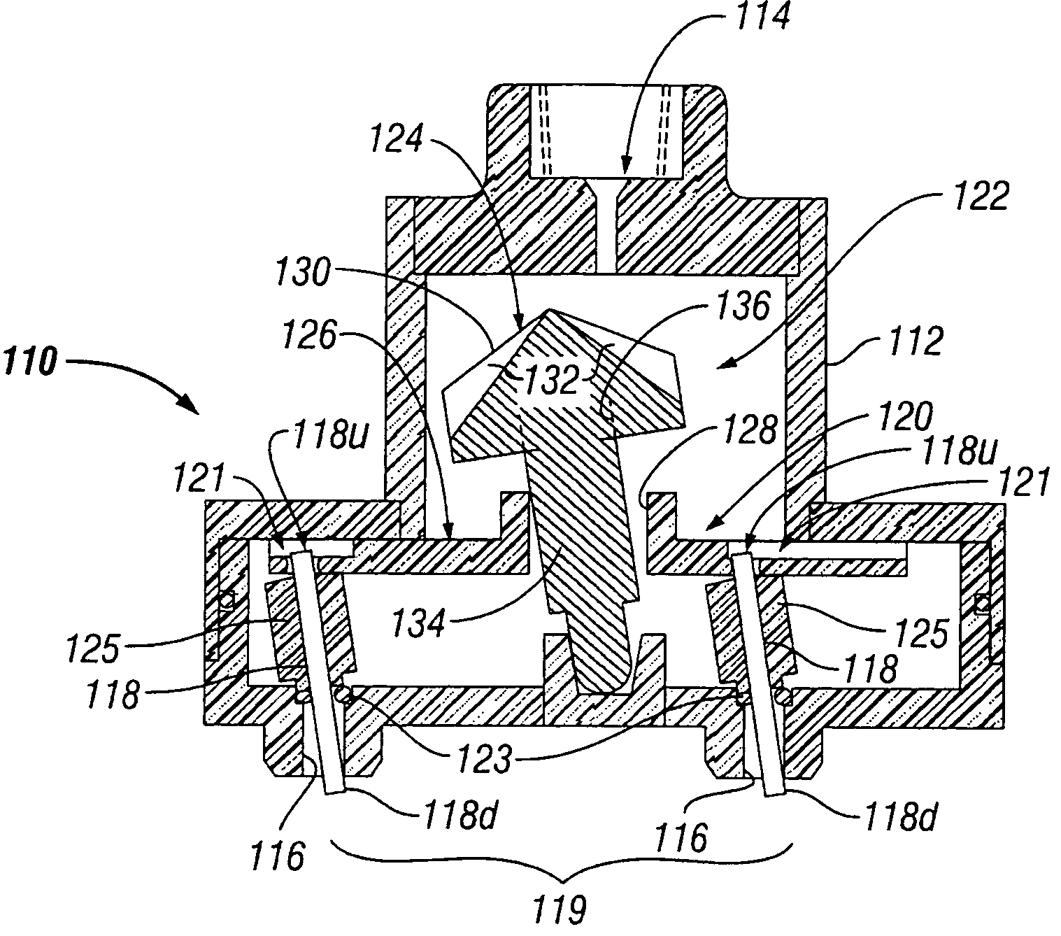
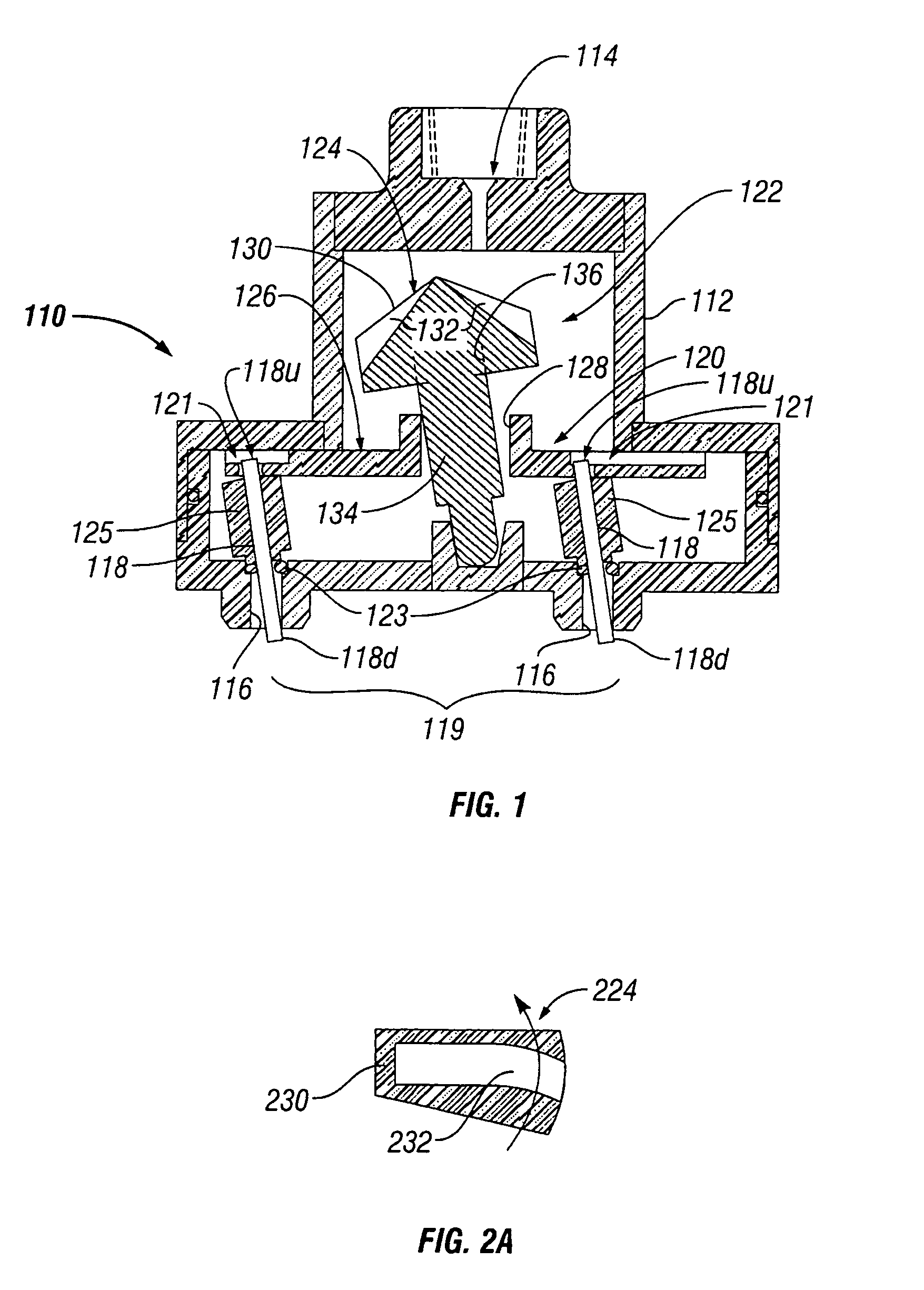
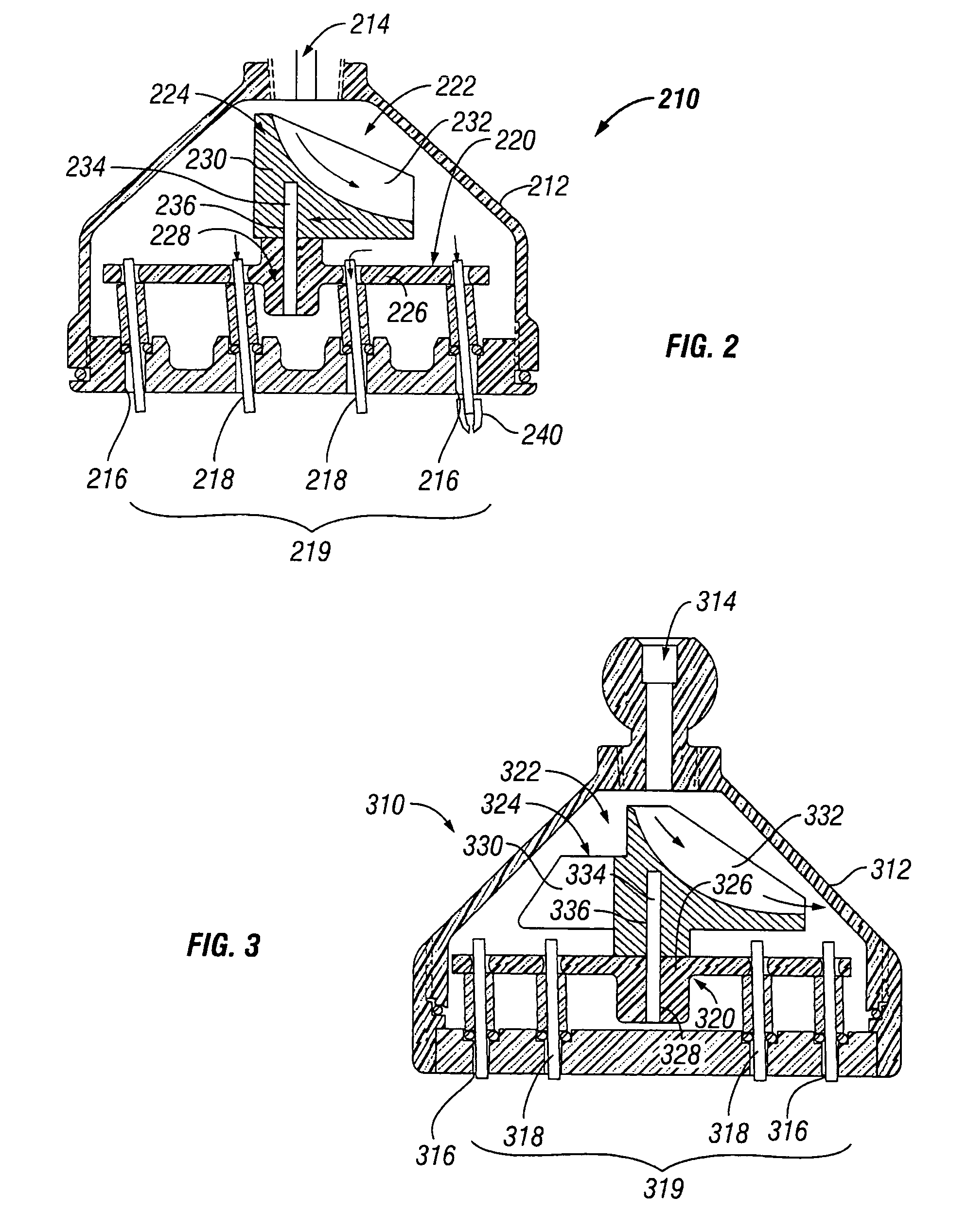
[0168]With reference now generally to FIGS. 1-68A (with “X” in the following reference numbers representing the number of the respective figure, e.g., “X10” means “1210” in FIG. 12), the present invention provides a spray apparatus X10, including a housing X12 having a fluid inlet X14 and a plurality of fluid outlets X16. The housing X12 is preferably made of a durable material known in the art to be suitable for use in showering applications, such as acrylonitrile butadiene styrene (ABS), acetal plastic, or an equivalent. It is presently preferred that at least a portion of the housing X12 is substantially cylindrical, as is shown more clearly in the housing embodiment 4112 of FIG. 41B, but this is not essential as shown, e.g., by the bell-shaped housing 4712 of FIG. 47, and the square-shaped housing 6612 in FIG. 66A.

[0169]A plurality of tubes X18 are further provided, each preferably being exclusively disposed in one of the fluid outlets X16, for dispensing fluid from the housing ...


PUM


Abstract

A spray apparatus comprises a housing having a fluid inlet, a plurality of tubes for dispensing fluid from the housing, and an integrating member operatively coupled to at least a subset of the plurality of tubes for effecting coordinated movement of the coupled tubes in response to movement of the integrating member. An actuator, such as a turbine or an adjustable control ring, is employed for inducing movement of the integrating member. The dispensing tubes may be flexible so as to allow for easy adjustment of the fluid-dispensing direction or shape by the application of a lateral force at one or more locations along the length of the tubes. The flexibility also facilitates amplified direction / shape changes (compared to rigid dispensing tubes) in the dispensed fluid streams, e.g., when the tubes are subjected to a lateral force on one side and an opposing pivoting force (axially offset from the lateral force) on the other side.

Description

CROSS-REFERENCE TO RELATED APPLICATION[0001]This application claims priority to U.S. patent application Ser. No. 10 / 917,691, filed on Aug. 13, 2004 now U.S. Pat. No. 7,278,591, and to U.S. Provisional Patent Application Ser. No. 60 / 699,723, filed on Jul. 15, 2005, the entire contents of which applications are hereby incorporated herein by reference.BACKGROUND OF THE INVENTION[0002]1. Field of the Invention[0003]The present invention relates to devices for distributing liquids such as water in desirable showering streams, such as showerheads and faucets.[0004]2. Background of the Related Art[0005]Showerheads are commercially available in numerous designs and configurations. While many showerheads are designed and sold for their decorative styling, there are many different showerhead mechanisms that are intended to improve or change one or more characteristic of the resulting water spray pattern. A particular spray pattern may be described by the characteristics of spray width, spray ...

Claims


Application Information

Patent Timeline
Patent Type & Authority Patents(United States)
IPC IPC(8): B05B3/02B05B1/34
CPCB05B1/185B05B3/008B05B3/0418B05B3/0422B05B3/0459B05B3/16
Inventor CLEARMAN, JOSEPH H.CLEARMAN, JACK F.
Owner FB GLOBAL PLUMBING GRP LLC
Why Eureka
Try Eureka