Resilient protector to protect a structure from an impact

a technology of resilient protectors and structures, applied in the direction of machine supports, domestic objects, applications, etc., can solve the problems of frequent damage to the structural supports of such racking systems, and achieve the effects of avoiding any stress concentration, and minimizing any stress concentration

Active Publication Date: 2010-08-10
INNOVATION CENT
View PDF21 Cites 31 Cited by
  • Summary
  • Abstract
  • Description
  • Claims
  • Application Information

AI Technical Summary

Benefits of technology

[0006]Preferably, each resiliently flexible joining portion adopts a tortuous path between the bumper member and the structure positioning member. The tortuous path is preferably curved so as to minimise any points of stress concentration along said path.
[0007]One end of said joining portion is preferably connected to the bumper member and the other end is preferably connected to the structure positioning member. Connection preferably occurs at a zone of connection so as to minimise stress concentrations in the protecting apparatus. Stress concentrations are preferably minimised by curving the zones of connection.
[0009]Preferably, at or adjacent to each of the first and second ends of the bumper member is tongue. The tongue is arranged in use to contact the structure when it is located in the opening and to facilitate retention of the protector apparatus about said structure. A tongue may also be formed on each of the first and second joining members to further facilitate retention of the protecting apparatus about said structure.

Problems solved by technology

The structural supports for such racking systems often become damaged because they are repeatedly impacted against by the fork lifts.

Method used


Image

  • Resilient protector to protect a structure from an impact
  • Resilient protector to protect a structure from an impact
  • Resilient protector to protect a structure from an impact

Examples


second embodiment

[0040]FIGS. 5 and 6 illustrate a protector apparatus 200 in accordance with the invention. The protector apparatus 200 adopts a slightly different shape to the protector apparatus 10. Additionally, strengthening ribs 201 have been provided at various locations along an inner surface 212d of the bumper member 212. The strengthening ribs 201 have been provided to control the flexure of the bumper member 212. A cross member 202 has also been provided to extend between the bumper member 212 and the structure positioning member 214. The cross member 202 is provided to enable advertising information or other information to be stamped or moulded onto the protecting apparatus 200.

[0041]As shown in FIG. 6, when the protector apparatus 200 is pushed onto the structural support 100 flexure of the protector apparatus 200 occurs. This results in some distortion of the shape of the protector apparatus 200.

third embodiment

[0042]FIGS. 7 and 8 illustrate a protector apparatus 300 in accordance with the invention. The protector apparatus 300 is similar to the apparatus 200 shown in FIGS. 5 and 6. However, it will be appreciated that the protector apparatus 300 includes tongues 224 to further facilitate retention of the protecting apparatus 300 about the structural support 100.

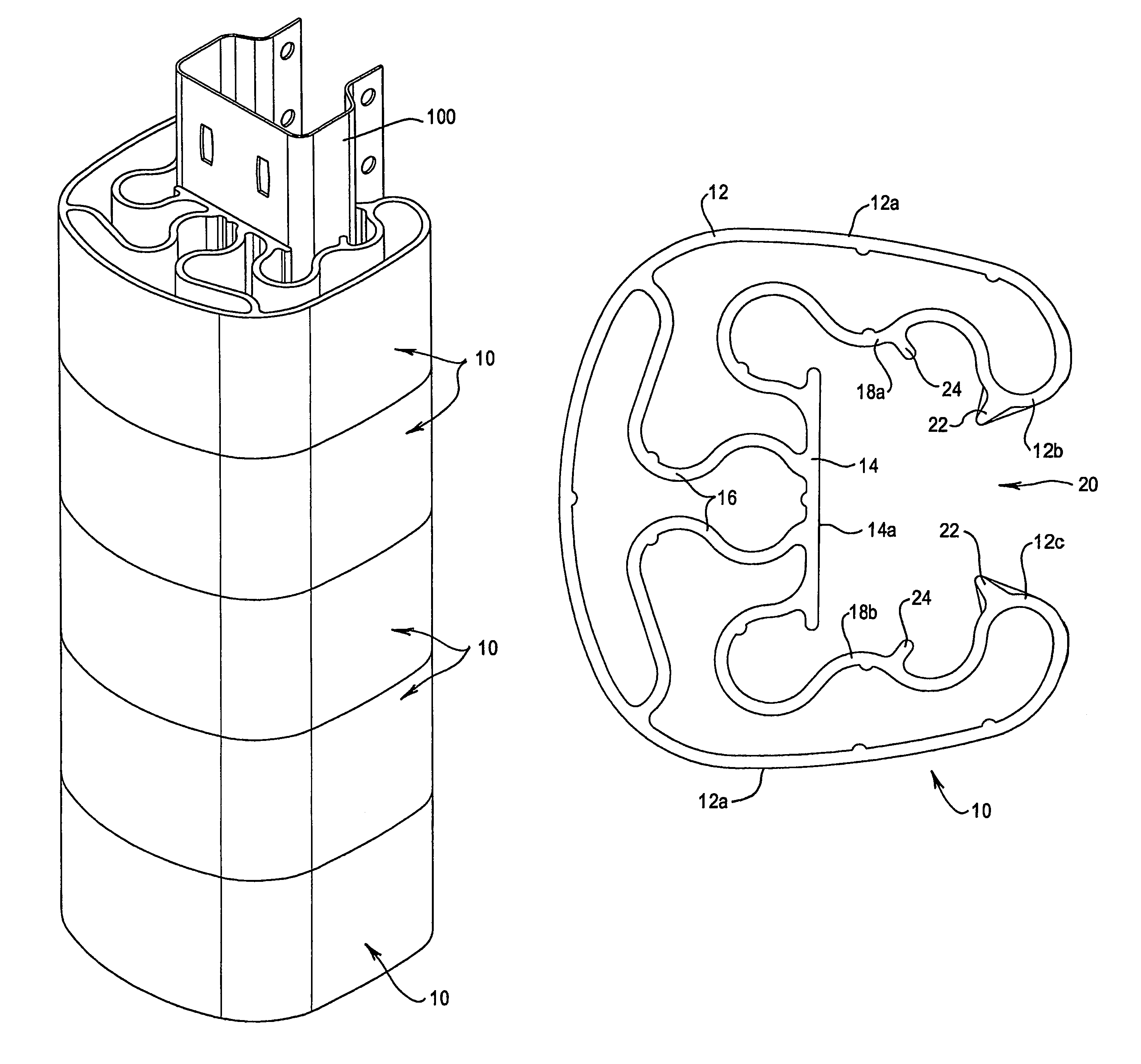
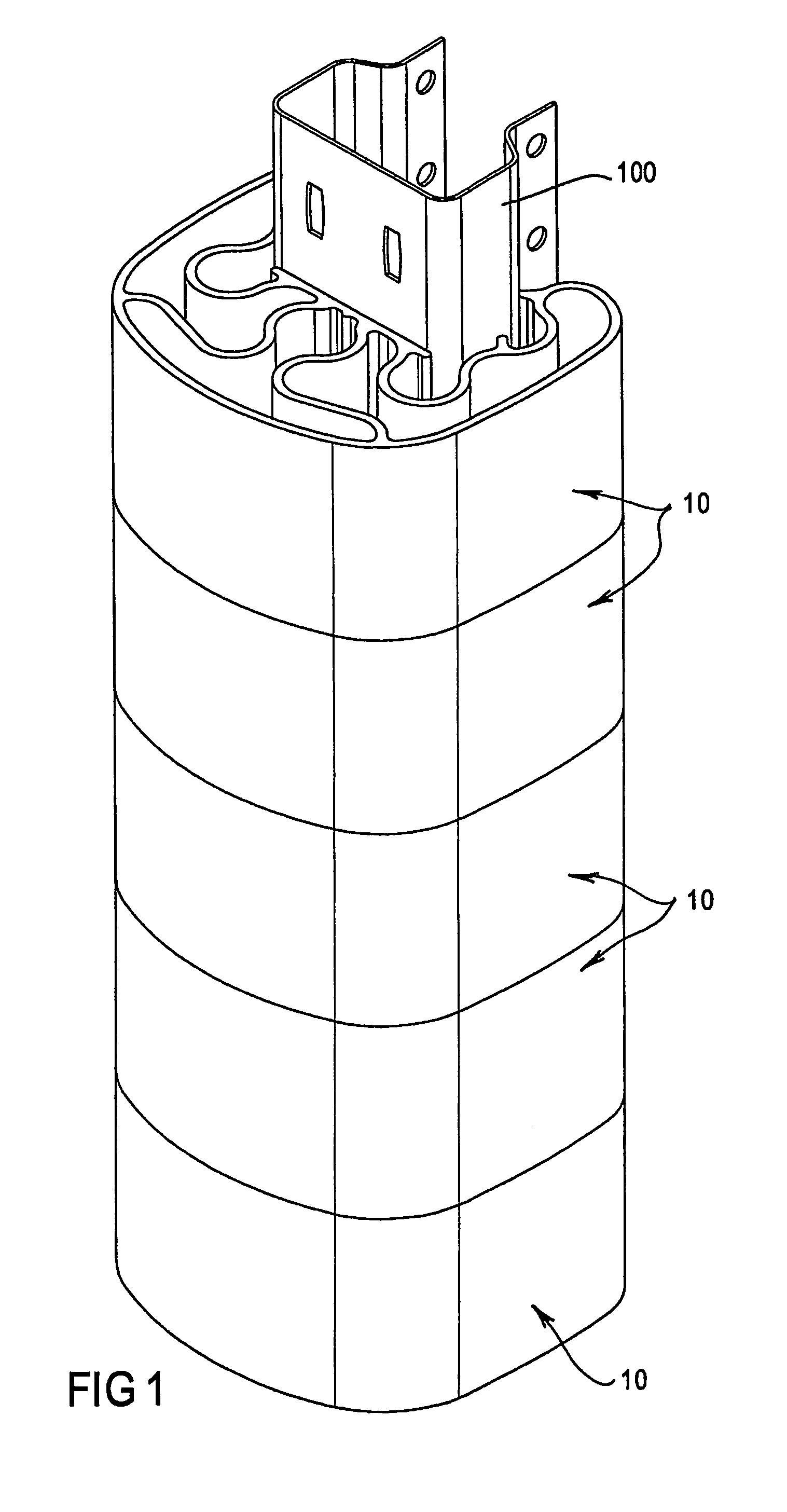
[0043]It will also be appreciated that different coloured or patterned protecting apparatus 10 could be provided. Thus, by stacking numerous protecting apparatus 100 one on top of the other, different patterns etc could be achieved.

[0044]It will be appreciated by those skilled in the art that the material from which the protecting apparatus is made may need to vary and be selected to accommodate different working environments. For example, different materials may need to be used if the protecting apparatus was used in an extremely cold environment (for example, a cold room) as compared to when the protecting apparatus was used in a...


PUM


Abstract

The invention relates to a protecting apparatus (10) for protecting a structure (100) from an impact. The protecting apparatus (10) is arranged to be mounted on the structure (100) and includes a bumper member (12), a structure positioning member (14) and at least one resiliently flexible joining portion (16). The structure positioning member (14) is arranged in use to be positioned in contact with or adjacent to a portion of the structure (100) being protected. The at least one resiliently flexible joining portion (16) extends between the bumper member (12) and the structure positioning member (14) so that when an outer surface (12a) of the bumper member (12) is impacted, the impact force is dissipated at least in part by flexure of the at least one joining portion (16).

Description

FIELD OF THE INVENTION[0001]The invention relates to a protecting apparatus for protecting structures from impact damage.BACKGROUND OF THE INVENTION[0002]In many warehouses, goods are stored in racking systems and are accessed by fork lifts or other vehicles. The structural supports for such racking systems often become damaged because they are repeatedly impacted against by the fork lifts. Various protective devices have been developed in an attempt to prevent or at least limit damage to such structural supports.[0003]The present invention seeks to provide an improved protecting apparatus which can be used to protect a wide variety of different structures.SUMMARY OF THE INVENTION[0004]According to the present invention there is provided a protecting apparatus for protecting a structure from an impact, said protecting apparatus being arranged to be mounted on the structure and including a bumper member, a structure positioning member and at least one resiliently flexible joining por...

Claims


Application Information

Patent Timeline
Patent Type & Authority Patents(United States)
IPC IPC(8): A47B95/00A47B95/04E01F15/14F16F7/00
CPCA47B95/043B65G1/02E01F15/141F16F7/00B65G2207/40
Inventor HUXTABLE, PAUL STEWARTPENDERGRAST, IAN HOWARD
Owner INNOVATION CENT
Why Eureka
Try Eureka