Method and system for manufacture and delivery of an emulsion explosive

a technology of emulsion explosives and manufacturing methods, applied in the direction of explosives, weaving, looms, etc., can solve the problems of increasing the risk involved in the delivery, adding a delivery pump, and significantly increasing the cost of conveying emulsion explosives to the intended location, so as to reduce the density

Active Publication Date: 2010-08-10
DYNO NOBEL INC
View PDF20 Cites 8 Cited by
  • Summary
  • Abstract
  • Description
  • Claims
  • Application Information

AI Technical Summary

Problems solved by technology

Therefore, any mechanical input into the emulsion explosive, such as the mechanical input from a delivery pump, undesirably increases the risks involved in the delivery.
In addition, the addition of a delivery pump significantly increases the cost in conveying the emulsion explosive to the intended location.

Method used


Image

  • Method and system for manufacture and delivery of an emulsion explosive
  • Method and system for manufacture and delivery of an emulsion explosive
  • Method and system for manufacture and delivery of an emulsion explosive

Examples


example one

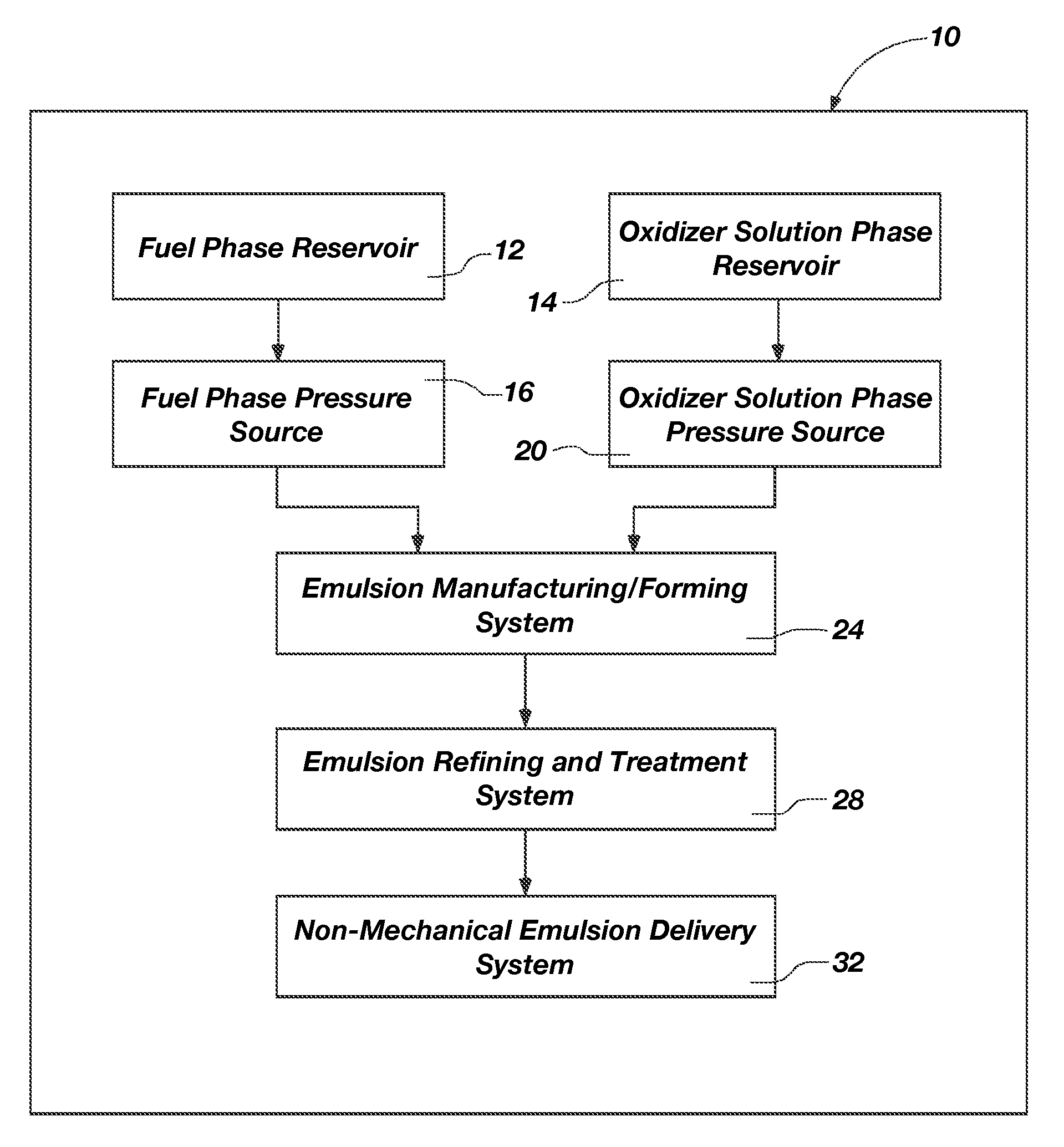
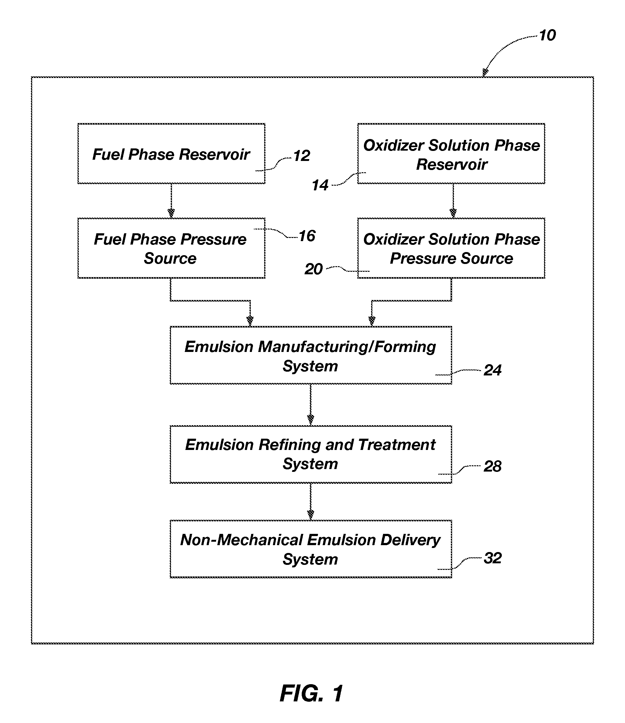
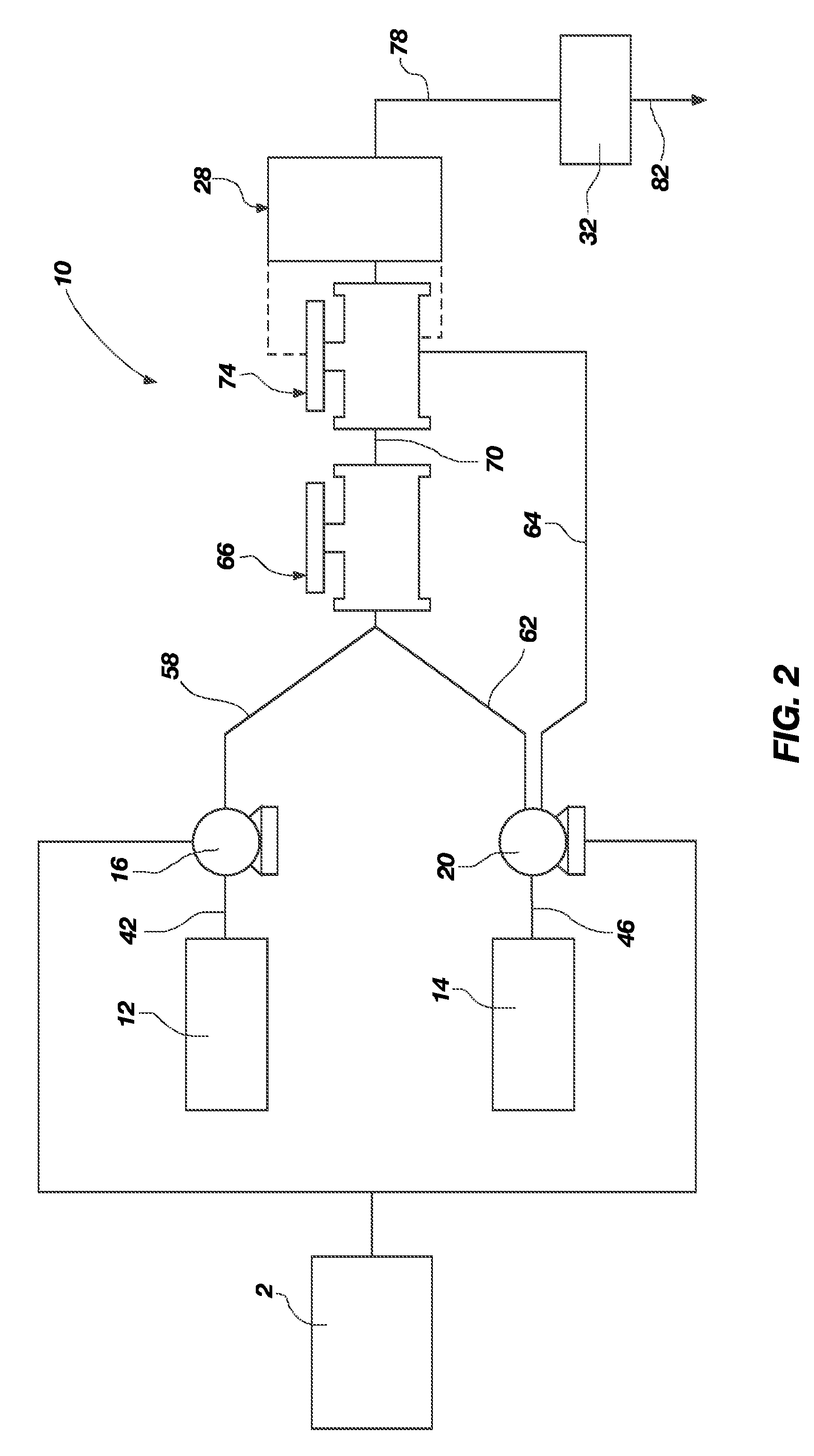
[0069]An emulsion explosive composition was formed at 500 pounds per minute (500 lbs. / min.). Fuel phase, with an emulsifier, was pumped through a first nozzle at a 30 pounds per minute (30 lbs. / min.) flow rate. A portion of oxidizer solution phase was pumped by a Waukesha oxidizer solution pump through a second nozzle at a 235 pounds per minute (235 lbs. / min.) flow rate. The oxidizer solution phase was split to more rapidly and efficiently form the emulsion. The first and second nozzles were oriented in a counter-opposing position with respect to one another so that their outlet ports or nozzle openings were directly facing one another. The initial pressures at each of the fuel phase and oxidizer solution phase pumps caused the fuel phase, with an emulsifier present therein, to impinge a portion of the oxidizer solution phase within a mixing chamber to form a high fuel or fuel-rich emulsion. The high fuel emulsion blend was then forced through a third nozzle oriented perpendicular t...

example two

[0070]This Example is similar to Example One. However, the nozzles and flow rates from the above example were sized down from 500 lbs / min. to achieve a 200 pounds per minute (200 lbs / min.) flow rate. In addition, fuel phase, with an emulsifier, was pumped by a gear pump through a first nozzle. Oxidizer solution phase was pumped by a high-pressure diaphragm pump through a second nozzle. The regular fuel phase pump was replaced with the gear pump to achieve the necessary flow rates at pressures to about 500 psig. The replacement of the Waukesha oxidizer solution pump with the high pressure diaphragm pump also provides the capability to deliver the desired flow rates at these elevated pressures.

[0071]Again, the first and second nozzles were oriented in a counter-opposing position with respect to one another so that their outlet ports were directly facing one another. The initial pressures at each of the fuel phase and oxidizer solution phase pumps caused the fuel phase, with an emulsif...


PUM

PropertyMeasurementUnit
pressureaaaaaaaaaa
pressureaaaaaaaaaa
residual pressureaaaaaaaaaa

Abstract

A method for manufacture and delivery of an emulsion explosive having a discontinuous oxidizer solution phase, a continuous fuel phase, and an emulsifier, the method comprising: (a) providing an emulsion manufacturing system; (b) conveying an oxidizer solution phase to the emulsion manufacturing system at a pre-determined pressure; (c) conveying a fuel phase to the emulsion manufacturing system at a pre-determined pressure; (d) forming an emulsion from the oxidizer solution and the fuel phases using only a portion of the pre-determined pressures so as to provide a usable residual pressure after the formation of the emulsion; and (e) utilizing the residual pressure to non-mechanically deliver the emulsion to a pre-determined location.

Description

BACKGROUND AND RELATED ART[0001]The present invention relates generally to explosives and explosive delivery systems, and more particularly to a method and system for manufacturing, sensitizing, and delivering an emulsion explosive, either on-site, in a plant, or to another intended location.[0002]On-site explosive emulsion manufacturing and delivery systems are known in the art. These systems utilize various fuel and oxidizer solution phase ingredients, along with various sensitizers, density reducing agents and other ingredients, to form an emulsion explosive. The system used to form the emulsion and to prepare it for delivery typically comprises various combinations of mechanical pumps, mixers, and other systems. In addition, once the emulsion is formed, a mechanical delivery pump, such as a progressive cavity pump, is required to actually deliver the emulsion. The mechanical delivery pump receives the formed emulsion and functions to mechanically convey the emulsion to the inten...

Claims


Application Information

Patent Timeline
Patent Type & Authority Patents(United States)
IPC IPC(8): C06B31/00D03D23/00D03D43/00
CPCC06B21/0008F42D1/10C06B47/145F42B12/72
Inventor HALANDER, JOHN B.NELSON, CASEY L.BONNER, CLARK D.
Owner DYNO NOBEL INC
Why Eureka
Try Eureka