
Design structure for improved memory column redundancy scheme

a design structure and column redundancy technology, applied in the field of integrated circuit memory devices, can solve the problems of large area overhead of this type of column redundancy, data path, but not part of access delay, and add delay to access tim

Inactive Publication Date: 2010-08-10
IBM CORP
View PDF11 Cites 0 Cited by
  • Summary
  • Abstract
  • Description
  • Claims
  • Application Information

AI Technical Summary

Benefits of technology

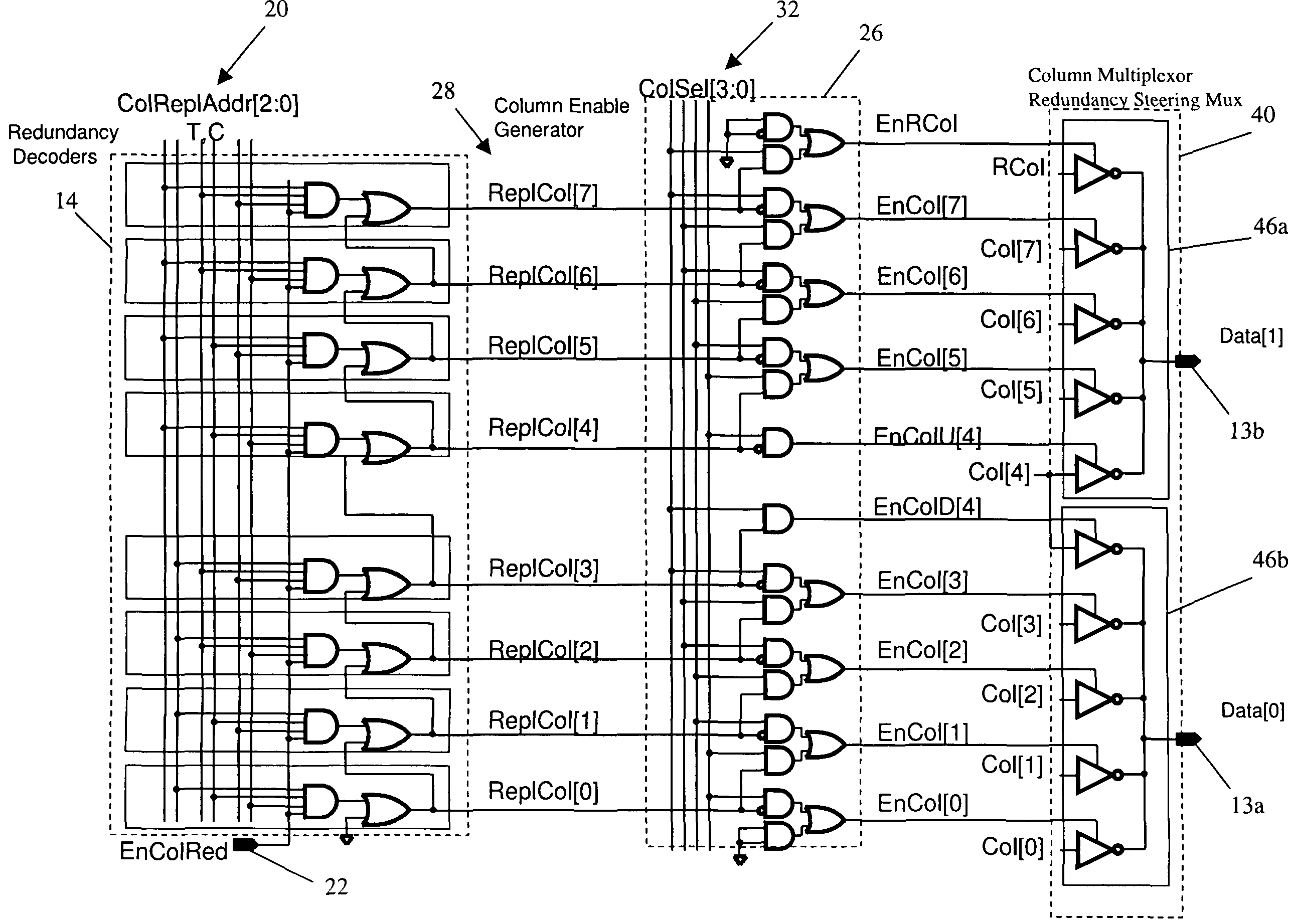
The present invention provides a design structure for a machine-readable medium used in a design process. This design structure includes a system for implementing a memory column redundancy scheme. The system includes a core array with multiple columns and a redundancy column for reading or writing information. The system also includes circuitry for steering around a defective column in the core array. The circuitry includes redundancy decoders and column enable generators to bypass the defective column and shift down every column within the core array. The system also includes a column multiplexor for providing a data path between one column and a data output line. The invention provides additional advantages and features over prior art.

Problems solved by technology

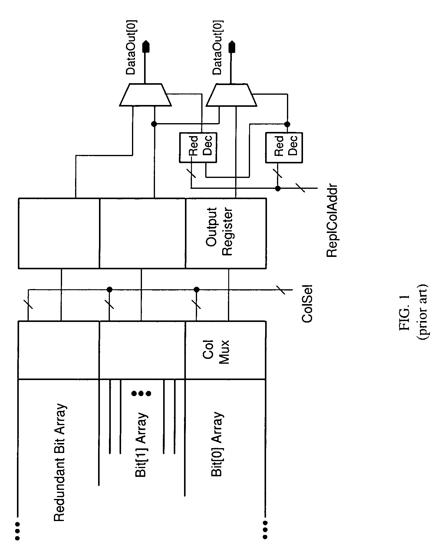
One of the drawbacks for this type of architecture is that the area overhead of this type of column redundancy is large because a full data bit is replicated.
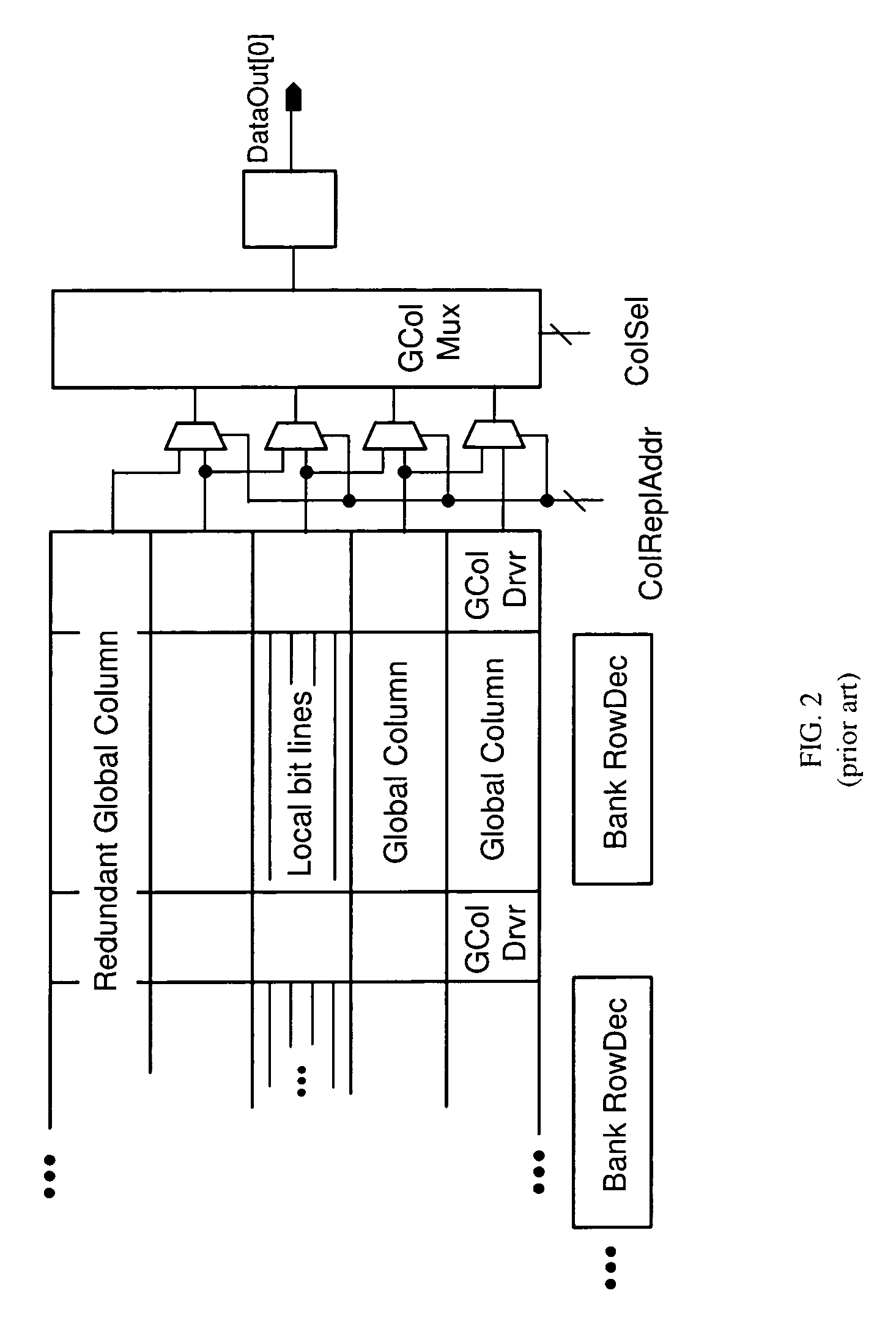
However, these two distinct muxes add delay to the access time.
The data path, however, is part of the access delay.

Method used


Image

  • Design structure for improved memory column redundancy scheme
  • Design structure for improved memory column redundancy scheme
  • Design structure for improved memory column redundancy scheme

Examples


Embodiment Construction

[0021]Exemplary embodiments of a system for implementing a memory column redundancy scheme and a method of using the same in accordance with the present invention will now be described with reference to the drawings. The exemplary embodiment of the system described herein is configured to send a column replace address signal to input lines of a plurality of redundancy decoders that correspond to a plurality of columns in a core array where the column replace address signal identifies the defective column in the core array. The exemplary embodiment of the system described herein is further configures to send an enable column redundancy signal to the plurality of redundancy decoders for activating a memory column redundancy scheme. The exemplary embodiment of the system described herein is further configured to bypass a defective column and shift down every column within a core array after the defective column consequently having a non-defective column take the place of the defective ...


PUM


Abstract

A design structure embodied in machine readable medium used in a design process includes a system for implementing a memory column redundancy scheme. The system comprises a core array having a plurality of columns and a redundancy column each configured for reading or writing a bit of information and circuitry for steering around a defective column in the core array, wherein the circuitry includes one column multiplexor, which results in having the memory column redundancy scheme include one multiplexing stage.

Description

CROSS-REFERENCE TO RELATED APPLICATIONS[0001]This application is a continuation-in-part application of U.S. Ser. No. 11 / 853,892, filed Sep. 12, 2007, the contents of which are incorporated by reference herein in their entirety.BACKGROUND OF THE INVENTION[0002]1. Field of the Invention[0003]This invention relates to integrated circuit memory devices, and, more particularly, to a design structure for a system implementing a memory column redundancy scheme.[0004]2. Description of Background[0005]Existing memory architectures with column redundancy typically have two levels of multiplexing, each providing its own contribution to memory access time. FIG. 1 illustrates an existing architecture. FIG. 1 generally illustrates a simple form of column multiplexing which involves completely replicating a bit of the memory word (here, a “bit” includes a memory array, column mux, and input and output circuit) such that, for example a 2K×16 RAM becomes a 2K×17 RAM; and selecting the full extra (re...

Claims


Application Information

Patent Timeline
Patent Type & Authority Patents(United States)
IPC IPC(8): G11C29/00G11C7/00
CPCG11C29/846G11C29/848
Inventor WISSEL, LARRY
Owner IBM CORP
Learn More