Frame structure and method for wavelength concatenated channel framing

a concatenated channel and frame structure technology, applied in the field of information networks, can solve the problems of inability to economically transport such high-speed datastreams (i.e., beyond 10 gbps) over long distances using currently-installed fiber-optic cabling

Active Publication Date: 2010-08-10
ADTRAN NETWORKS SE
View PDF14 Cites 8 Cited by
  • Summary
  • Abstract
  • Description
  • Claims
  • Application Information

AI Technical Summary

Problems solved by technology

While the port speeds of routers can (and likely will) be increased beyond 10 Gbps, the transport systems presently in place are unable to transport such high-speed) datastreams (e.g., a 40 Gbps (or greater) datastream) using currently-installed fiber-optic cabling, at least without expensive (and frequent) regeneration.
This inability to economically transport such higher-speed datastreams (i.e., beyond 10 Gbps) over long distances using currently-installed fiber-optic cabling is an obstacle to deployment of high-speed transport at the network core.
Moreover, the efficiency (the amount of data versus the overall size of a frame) provided by SONET is somewhat less than desirable.
This means that 3.8% of the available bandwidth is consumed by overhead (or is unused).
Given the costs associated with providing bandwidth at such data rates, this overhead represents appreciable lost revenues.
Although this seems logical from the perspective of the connection, this alternative is not very scalable or economical because the IP forwarding table per port increases linearly and the total memory required for the forwarding table increases as N2 (where N=number of ports).
The large port count also involves larger space and power requirements that add to the cost of this solution.

Method used


Image

  • Frame structure and method for wavelength concatenated channel framing
  • Frame structure and method for wavelength concatenated channel framing
  • Frame structure and method for wavelength concatenated channel framing

Examples


example payload

and PDUs

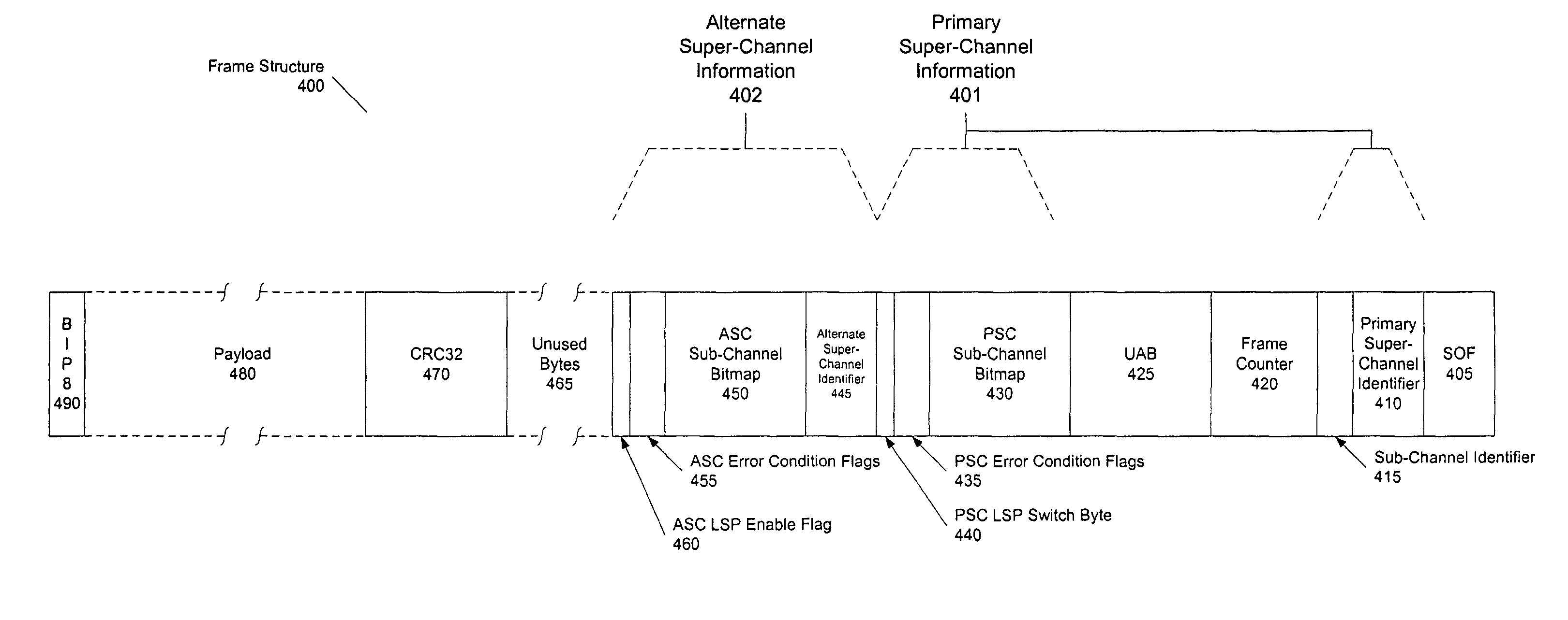
[0139]FIGS. 16A, B, C and D together give an example of an overall payload structure that can be used in frame structure 400 of FIG. 4, and so correspond to payload 480 as discussed with regard thereto. FIG. 16A illustrates a payload 1600 that is made up of a number of payload data units (PDUs) that each contain PDU information (depicted in FIG. 16A as one of PDU information 1605(1)-(N)), data length information (depicted in FIG. 16A as data lengths 1610(1)-(N)), and the data being transported (depicted in FIG. 16A as data 1615(1)-(N)). In one embodiment, PDU information includes parity information (e.g., a parity bit; not shown), a partial PDU indicator (not shown) and a queue identifier (not shown).

[0140]In the embodiments depicted herein, a payload such as payload 1600 is 155,439 bytes in length, and is made up of 303 PDUs. Each PDU carries up to 512 bytes of raw data. If the raw data in the PDU is less that 512 bytes, then the PDU carries up to 510 bytes of raw data and ...


PUM


Abstract

A method, device, and apparatus that provide a means for generating a network frame that provides information related to one or more super-channels for data transmission, which are comprised of one or more sub-channels for data transmission, over which the network frame is transmitted are disclosed.

Description

CROSS-REFERENCES TO RELATED APPLICATIONS[0001]This application is a continuation of U.S. patent application Ser. No. 10 / 086,273 now U.S. Pat. No. 7,237,035, entitled “FRAME STRUCTURE AND METHOD FOR WAVELENGTH CONCATENATED CHANNEL FRAMING,” filed on Feb. 20, 2002, and having Rajendra R. Damle as the inventor, which is a continuation-in-part of patent application Ser. No. 10 / 074,264, entitled “TRANSPORT OF HIGH-BANDWIDTH DATASTREAMS OVER A NETWORK,” filed on Feb. 12, 2002, and having R. Damle, Y. Lee, W. Szeto, R. Butler and H. M. Zadikian as inventors, which, in turn, claims priority from the following provisional patent applications under 35 U.S.C. §119(e):[0002]1. Provisional Patent Application Ser. No. 60 / 268,237, entitled “EVOLUTION OF CARRRIER BACKBONE DATA NETWORK NEW REQUIREMENTS”, filed Feb. 12, 2001, and naming R. R. Damle as inventor;[0003]2. Provisional Patent Application Ser. No. 60 / 268,180, entitled “END-TO-END NETWORK ARCHITECTURE FOR THE NEXT GENERATION IP NETWORK”, fi...

Claims


Application Information

Patent Timeline
Patent Type & Authority Patents(United States)
IPC IPC(8): G06F13/00
CPCH04J3/0608H04L45/50
Inventor DAMLE, RAJENDRA R.
Owner ADTRAN NETWORKS SE
Why Eureka
Try Eureka