Drive apparatus for sliding member

a technology of sliding member and drive apparatus, which is applied in the direction of dynamo-electric components, dynamo-electric machines, construction, etc., can solve the problems of increased tensioner size and inability to smoothly move the driven member to be opened and closed, and achieve the effect of reducing the size and eliminating the sag of the cabl

Inactive Publication Date: 2010-08-17
MITSUI KINZOKU ACT
View PDF7 Cites 10 Cited by
  • Summary
  • Abstract
  • Description
  • Claims
  • Application Information

AI Technical Summary

Benefits of technology

[0005]It is, therefore, an object of the present invention to provide a sliding drive apparatus devised to decrease the size, and to eliminate sag of a cable surely.

Problems solved by technology

Consequently, there are problems that size of the tensioner is increased, and that the driven member is not smoothly moved to be opened and closed for excessive tensioning force applied to the cable.

Method used


Image

  • Drive apparatus for sliding member
  • Drive apparatus for sliding member
  • Drive apparatus for sliding member

Examples


Embodiment Construction

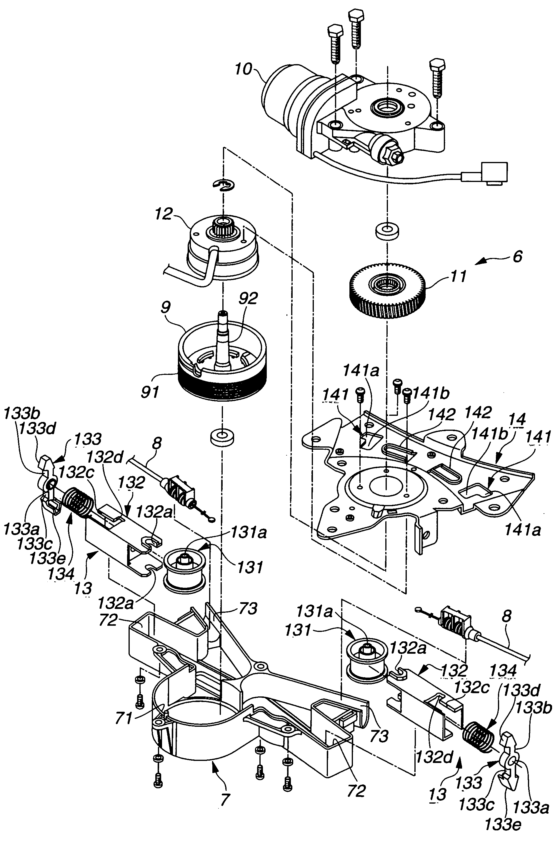
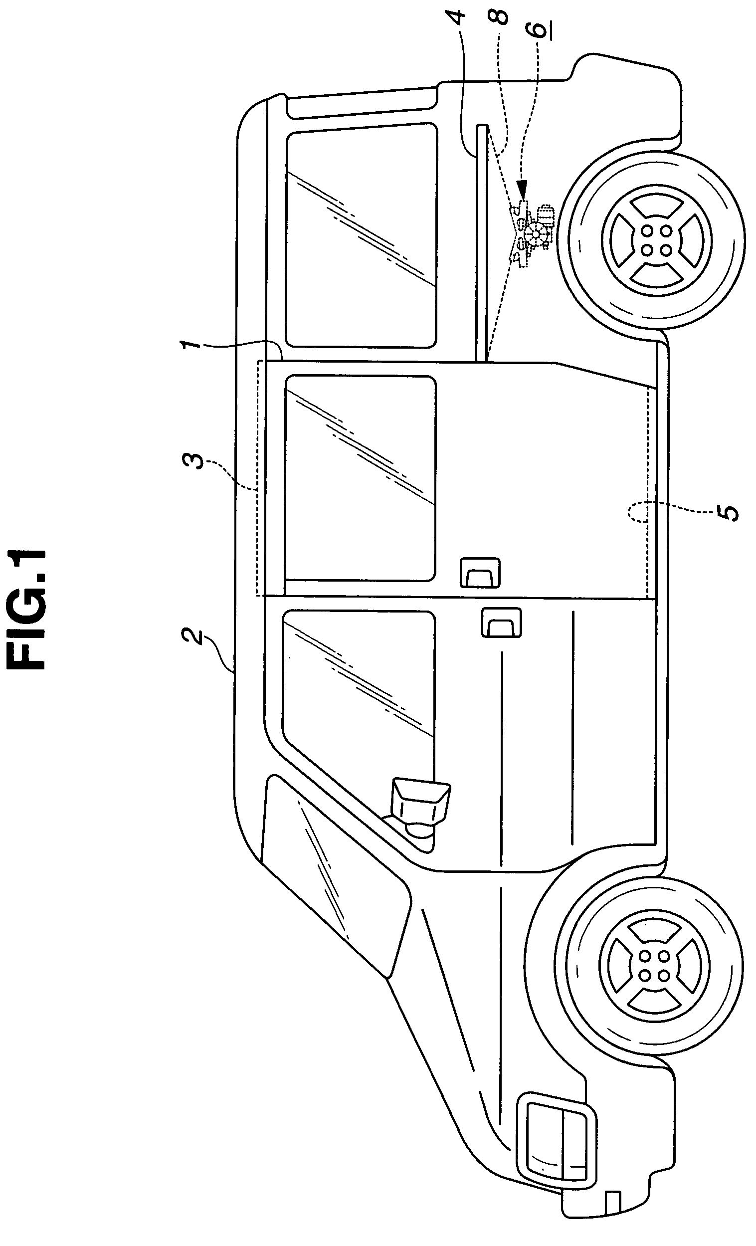
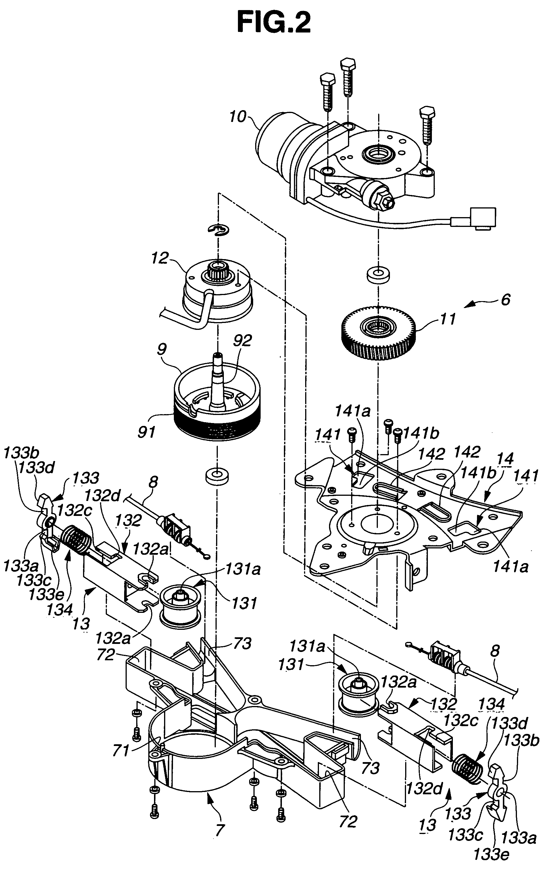
[0020]Hereinafter, an embodiment according to the present invention will be illustrated with reference to the drawings. FIG. 1 is a side view showing a vehicle which employs a sliding drive apparatus according to an embodiment of the present invention. FIG. 2 is an exploded perspective view showing the sliding drive apparatus. FIG. 3 is an enlarged perspective view showing a main part. FIG. 4 is a side view showing the sliding drive apparatus. FIG. 5 is an enlarged side view showing the main part in a temporarily assembled state. FIG. 6 is a lateral sectional view taken along a section line VI-VI of FIG. 5. FIG. 7 is a longitudinal sectional view taken along a section line VII-VII of FIG. 5. FIG. 8 is an enlarged side view showing the main part in the way of the assembly operation. FIG. 9 is an enlarged side view showing the main part after completion of the assembly operation. FIG. 10 is a lateral sectional view taken along a section line X-X of FIG. 9. FIG. 11 is a longitudinal se...


PUM


Abstract

A driving apparatus for a sliding member includes a housing, a cable, a drum to move the cable to open and close the sliding member, a motor arranged to drive the drum, and a tensioner supported by the housing arranged to provide a tensioning force to the cable, the tensioner is arranged: to be switched from a first state where an urging force of a spring is stored to a second state where the urging force of the spring is released, to be moved from a first position where the tensioner does not provide the tensioning force to the cable to a second position where the tensioner provides an initial tensioning force to the cable when the tensioner is in the first state, and to be fixed in the second position and to be switched to the second state to provide the tensioning force to the cable by the urging force of the spring.

Description

BACKGROUND OF THE INVENTION[0001]This invention relates to a sliding drive apparatus arranged to open and close a driven member supported by a vehicle body, by a power from a motor.[0002]A Published Japanese Patent Application Publication No. 2004-300827 shows a sliding drive apparatus includes a cable connected to a driven member such as a sliding door supported by a vehicle body to be opened and closed; a drum capable of winding the cable; a motor arranged to drive the drum; and a tensioner arranged to provide a tensioning force to the cable by eliminating sag of the cable. The sliding drive apparatus is arranged to wind the cable around the drum by rotating the drum by the motor, and thereby to move the driven member to be opened and closed.[0003]In this sliding drive apparatus, when the cable is connected to the driven member, the tensioner is temporarily held, against an urging force of a spring, in a non-tensioning region that does not provide the tensioning force to the cable...

Claims


Application Information

Patent Timeline
Patent Type & Authority Patents(United States)
IPC IPC(8): E05F11/00
CPCH02K7/1004H02K7/116H02K7/14E05Y2900/531
Inventor MIYAGAWA, MASAZUMISHIMIZU, MASASHIOKUYAMA, KEIICHIRO
Owner MITSUI KINZOKU ACT
Why Eureka
Try Eureka