Electro-active ophthalmic lens having an optical power blending region
What is AI technical title?
AI technical title is built by Patsnap AI team. It summarizes the technical point description of the patent document.
a technology of optical power blending and ophthalmic lens, applied in the field of electroactive optics, can solve problems such as objectionable image jumps for patients
Inactive Publication Date: 2010-08-17
E-VISION OPTICS LLC
View PDF269 Cites 10 Cited by
Summary
Abstract
Description
Claims
Application Information
AI Technical Summary
This helps you quickly interpret patents by identifying the three key elements:
Problems solved by technology
Method used
Benefits of technology
Problems solved by technology
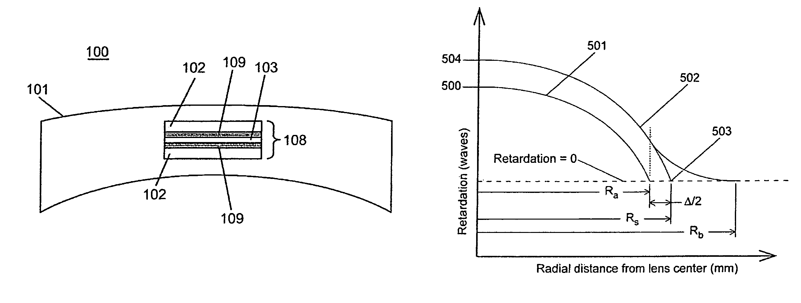
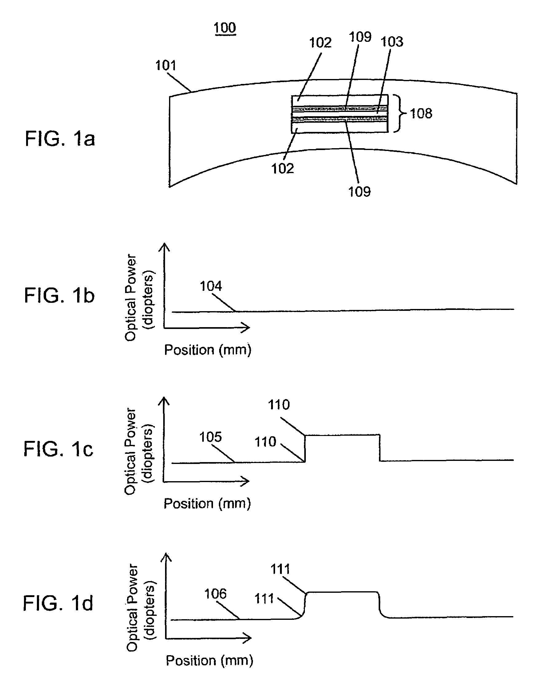
This discontinuity in optical power results in an image jump that may be objectionable to patients.
Method used
Image
Click on the blue label to locate the original text in one second.
Reading with bidirectional positioning of images and text.
Examples
example
[0092]It is to be understood that the following example of the present invention is not intended to restrict the present invention since many more modifications may be made within the scope of the claims without departing from the spirit thereof
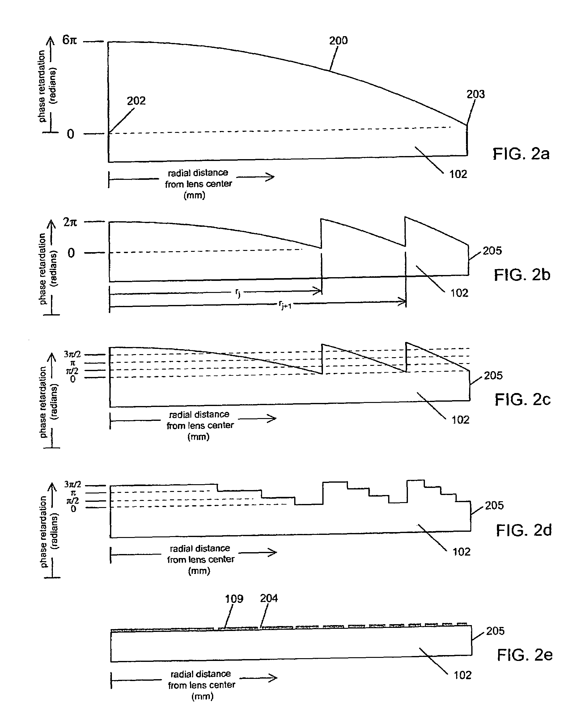
[0093]A prophetic example of an embodiment of the present invention is illustrated in FIGS. 7a-7d. Consider a lens with a desired focal length fo of 0.5 m (+2.0 diopters) at a wavelength λo of 0.555 μm. Said lens has a required diameter of constant add power of 15 mm (Ra=7.5 mm) and a 2 mm optical power blending region (Δ=2.0 mm, Rb=9.5 mm). As with the previous example, it is desired, for the illustrative example herein, to obtain an even, integer number of full wave Fresnel zones, so the focal length is adjusted to 0.4931 m (+2.028 diopters). Given these parameters, a third order blending polynomial is chosen and equation 7a is used to generate phase profile values from r=Ra to r=Rb and equation 5a is used to generate lens phase profile val...
PUM
Property
Measurement
Unit
electrical potential
aaaaa
aaaaa
diameter
aaaaa
aaaaa
thickness
aaaaa
aaaaa
Abstract
The present invention generally relates to an electro-active optic incorporating a blend region between two regions each having different optical properties.
Description
CROSS REFERENCE TO RELATED APPLICATIONS[0001]This application is a continuation in part of U.S. patent application Ser. No. 11 / 091,104, titled “EA Spectacles” filed on 28 Mar. 2005, now U.S. Pat. No. 7,188,948 which is, in turn, a continuation of U.S. patent application Ser. No. 09 / 602,013, filed Jun. 23, 2000, now U.S. Pat. No. 6,619,799, and which, in turn, claims priority to the following U.S. Provisional Patent Applications, all of which are hereby incorporated by reference in their entirety:[0002]Ser. No. 60 / 142,053, titled “Electro-Active Spectacles”, filed 2 Jul. 1999;[0003]Ser. No. 60 / 143,626, titled “Electro-Active Spectacles”, filed 14 Jul. 1999;[0004]Ser. No. 60 / 147,813, titled “Electro-Active Refraction, Dispensing, & Eyewear”, filed 10 Aug. 1999;[0005]Ser. No. 60 / 150,545, titled “Advanced Electro-Active Spectacles”, filed 25 Aug. 1999;[0006]Ser. No. 60 / 150,564, titled “Electro-Active Refraction, Dispensing, & Eyewear”, filed 25 Aug. 1999; and[0007]Ser. No. 60 / 161,363, t...
Claims
Application Information
Patent Timeline
Application Date:The date an application was filed.
Publication Date:The date a patent or application was officially published.
First Publication Date:The earliest publication date of a patent with the same application number.
Issue Date:Publication date of the patent grant document.
PCT Entry Date:The Entry date of PCT National Phase.
Estimated Expiry Date:The statutory expiry date of a patent right according to the Patent Law, and it is the longest term of protection that the patent right can achieve without the termination of the patent right due to other reasons(Term extension factor has been taken into account ).
Invalid Date:Actual expiry date is based on effective date or publication date of legal transaction data of invalid patent.
Patent Type & AuthorityPatents(United States)
IPC IPC(8): G02C7/06G02F1/1335G02F1/29
CPCG02C7/06G02C7/083G02C2202/20
InventorSTEWART, WILBER C.MCGINN, JOSEPH T.HADDOCK, JOSHUA N.KOKONASKI, WILLIAMIYER, VENKATRAMANI S.BLUM, RONALD D.

