Besides the size, expense and unwieldiness of this structure, it does little to control the actual movement of the
golf club and does not specify how to determine the ideal swing plane.
This large mechanism is complex and does not control the important link between the club grip and club head.
Further, the disclosure does not specify how to align the rotor to the ideal swing plane.
However, the inherent flexibility in the large
system of mechanical linkages prevents precise control of the swing plane, whether or not it is ideal.
This
system purports to help users improve timing and release of hands, but actually inhibits the type of ball striking that compresses the ball between the turf and club face that is universally recommended for irons.
Further, the added weight of the
system disrupts normal feel of the golf club.
No training system that attempts to control the motion of the golf club works for all users.
They all suffer from the disadvantages that the mechanisms, rather than the golfer, control the motion of the club and the golfer's experience with the system is different than the real-world without it.
both on the practice range and on a real golf course, but no real golfer wants to run the risk of the hinge breaking during a real golf swing, turning a bad swing into a catastrophic swing.
Further, this system does not allow the golfer to practice with his or her own clubs.
The major shortcoming of this system and numerous similar systems is that they do not address the
mechanics of actually making the club face follow the desired path and they do not account for the
vertical motion of the club head through the ball and into the turf.
The
laser is intended to follow a path traced on a training mat on the ground, and in so doing help the golfer keep the club on an ideal swing The disadvantages of this and similar systems are that they can interfere with the golfer's hands and it is difficult to precisely align the
laser with the golf shaft.
Further, such systems direct the eyes of the golfer away from the ball during the golf swing.
The problems with this system are that it is difficult to precise align the dome with the shaft to obtain accurate, consistent readings, and there is no unique position of the bubble in the dome that corresponds to the preferred
shaft alignment to follow an ideal swing plane.
The major shortcoming of this system is that it does not provide the golfer with any new useful information and it ignores the more critical angle that the shaft makes with the ground.
Further, Spitzer's inventions do not assure that the club face is square with the ball and pointing toward the target, but only that the
toe of the club is vertical.
The major problems with this system are that it relies on the user correctly judging when the two shafts are parallel, and it is not practical to use the system during actual play.
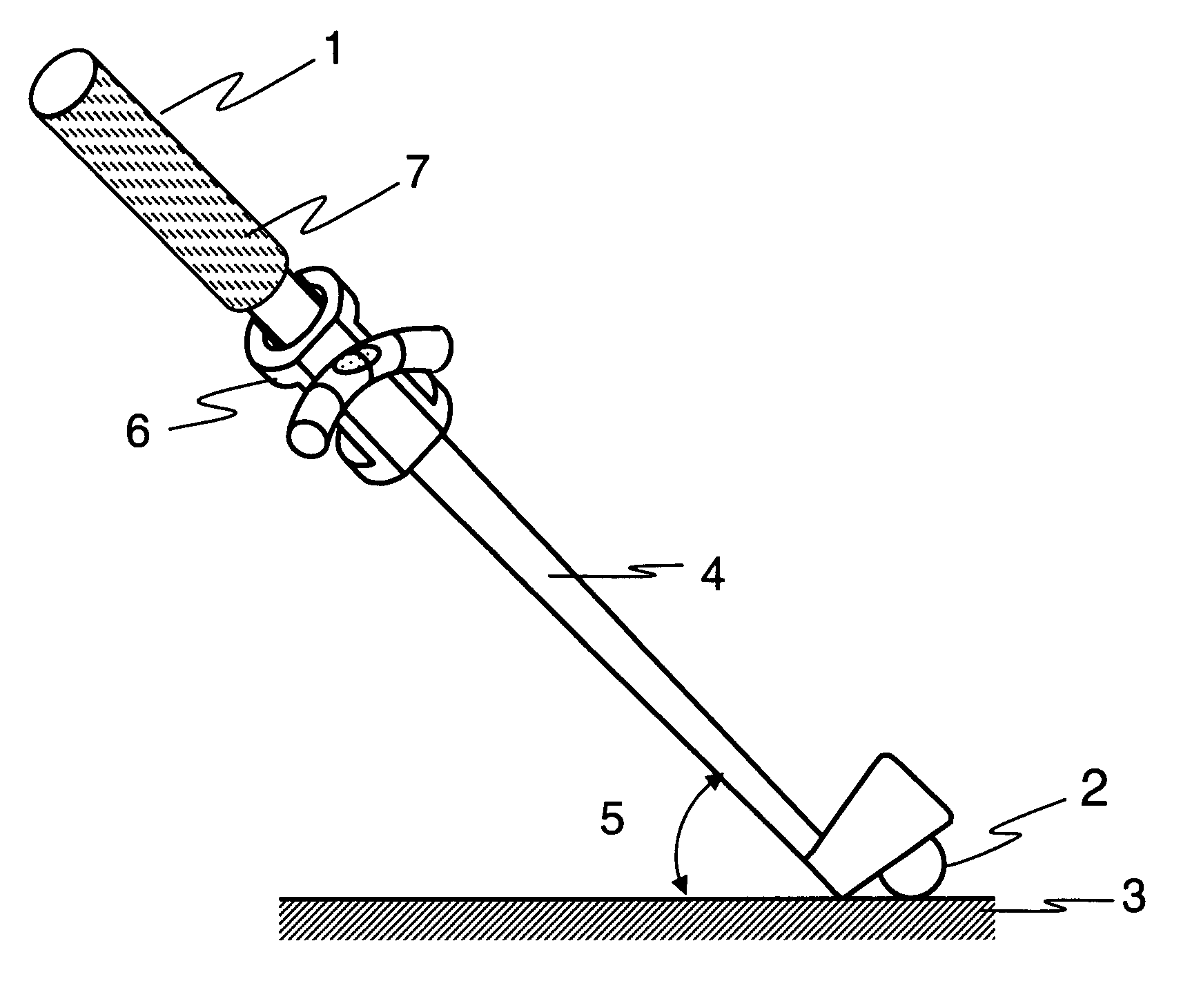
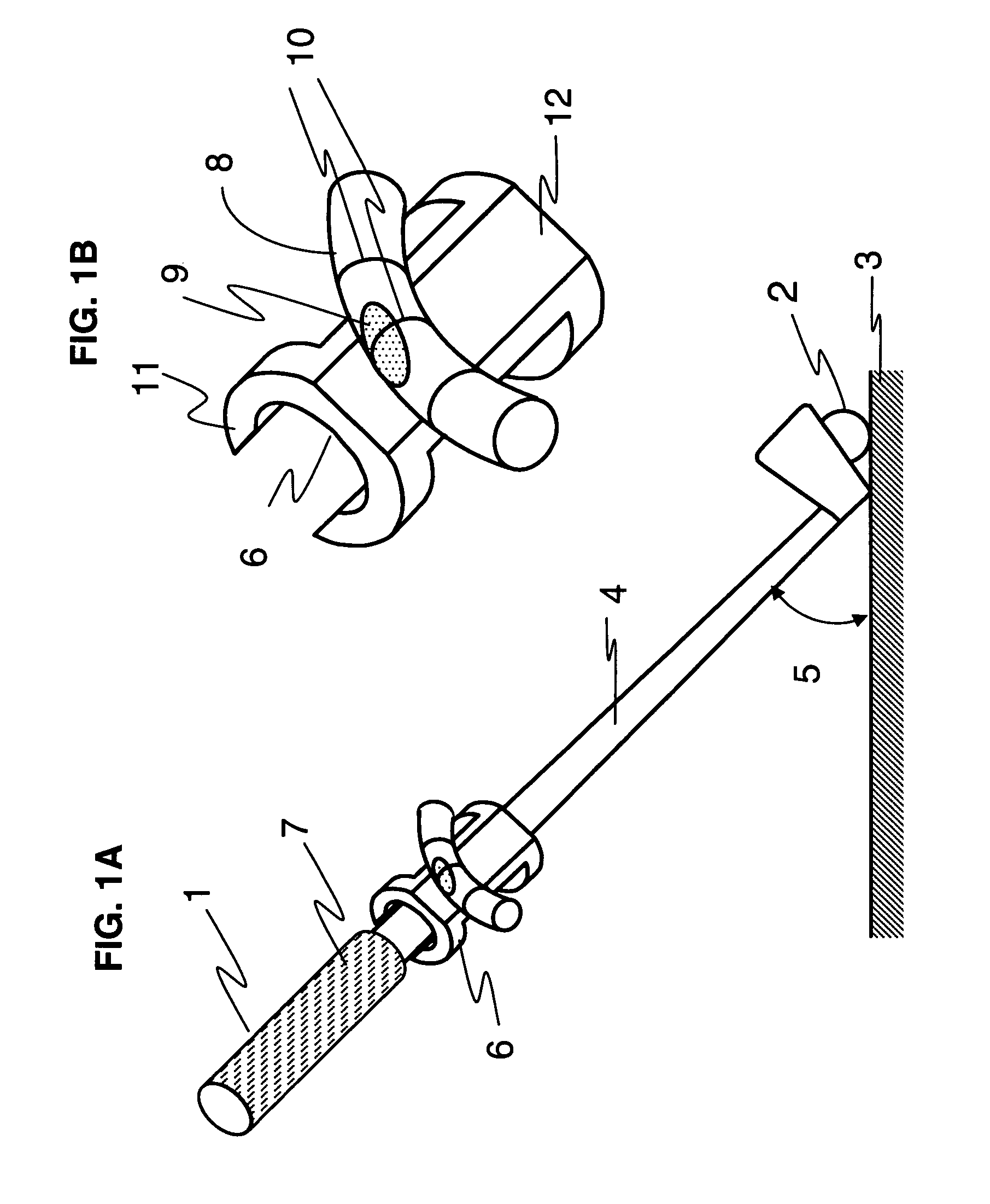
Such high shaft angles increase both ball spin and
launch angle, leading to shorter drives and flight trajectories more susceptible to hooks and slices.
Deviations from the 45 degree angle on the low side also have negative consequences.

