Balance exercise machine

a technology of exercise machine and seat, which is applied in the field of balance exercise machine, can solve the problems of insufficient motion, short stroke of seat motion, and dissatisfaction of users, and achieve the effect of widening the stroke of seat motion and increasing the pattern of motion

Inactive Publication Date: 2010-08-17
MATSUSHITA ELECTRIC WORKS LTD
View PDF35 Cites 10 Cited by
  • Summary
  • Abstract
  • Description
  • Claims
  • Application Information

AI Technical Summary

Benefits of technology

[0006]A purpose of the present invention is to provide an improved balance exercise machine which enables to increase patterns of motion and to widen a stroke of the motion of the seat with a compact configuration.
[0008]According to such a configuration, when the extendable and contractible mechanism is driven, a distance between the swing mechanism and the seat can be expanded or contracted. For example, when the extendable and contractible mechanism is extended, the stroke of the swing motion of the seat can be expanded, so that the balance exercise machine which enables to increase the patterns of the motion and to widen the stroke of the motion of the seat can be realized. Furthermore, when the extendable and contractible mechanism is driven in conjunction with the swing mechanism, the patterns of the motion of the seat can be increased much more.

Problems solved by technology

The conventional balance exercise machine having the compact configuration, however, has disadvantages that patterns of motion is not enough and a stroke of the motion of the seat is a little shorter.
Thus, if the trainee has habituated to the exercise, he or she may feel dissatisfaction.

Method used


Image

  • Balance exercise machine
  • Balance exercise machine
  • Balance exercise machine

Examples


Embodiment Construction

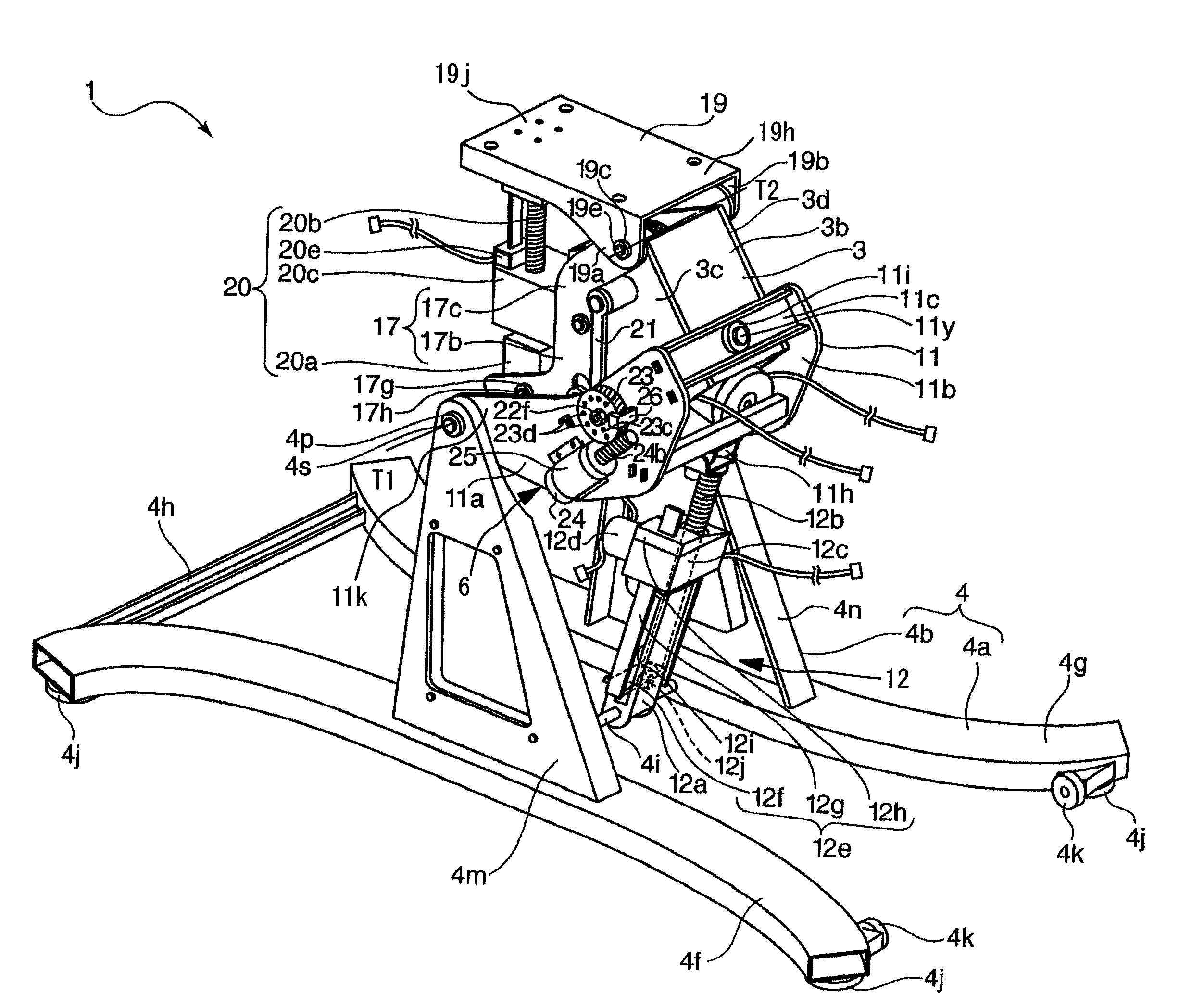
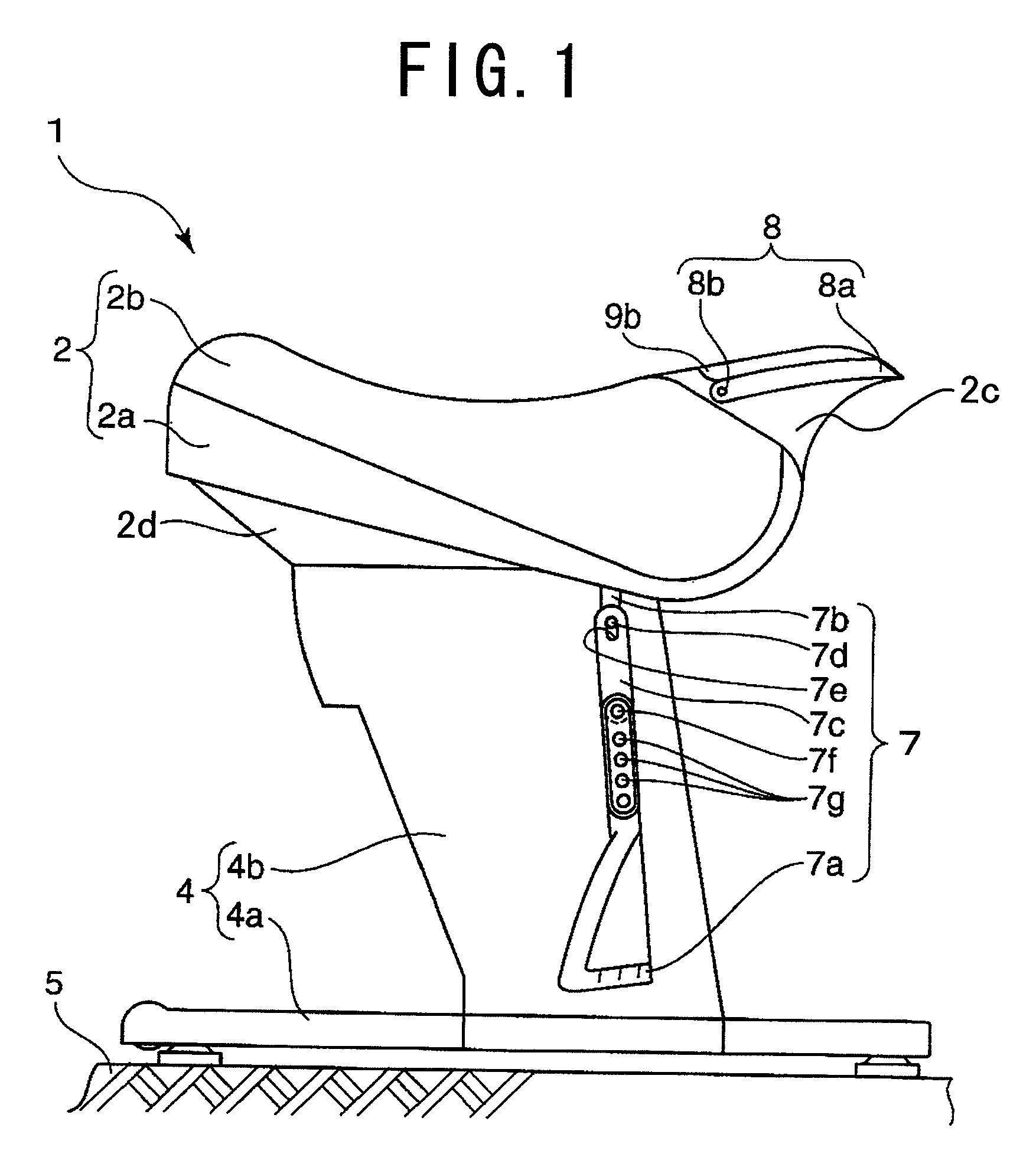
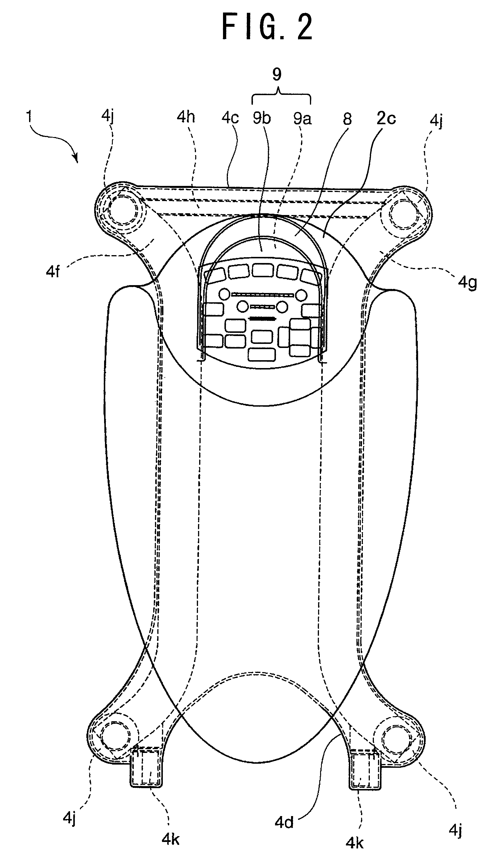
[0043]A balance exercise machine in accordance with an embodiment of the present invention is described with reference to the figures. FIG. 1 shows an entire configuration of a balance exercise machine 1 in accordance with the first embodiment. FIG. 2 is a plain view of the balance exercise machine 1. FIG. 3 shows a configuration of a driving mechanism of the balance exercise machine 1. FIG. 4 is a sectional front view along A-A line in FIG. 3. FIG. 5 is an exploded perspective view of the balance exercise machine 1 watched from a right rear side in FIG. 1.

[0044]The balance exercise machine 1 is comprised of a seat 2 which has a substantially horseback shape or a saddle shape and on which a trainee sits and a pedestal 4 which is disposed on a floor 5 and supports the seat 2 and so on. The seat 2 is configured to have a seat base 2a and a cushion 2b attached to the seat 2a.

[0045]A pair of stirrups 7 is hung down from both front sides of the seat 2 (in FIGS. 2 to 5, they are omitted ...


PUM


Abstract

In a balance exercise machine (1), a swing mechanism (3) that swings a seat (2) in both of an anteroposterior direction (direction X) and a widthwise direction (direction Y) is rotatably supported on a supporting unit (119 around a predetermined rotation axis (T0). A first inclination mechanism (12) that stands up or down the rotation axis (T0) is provided between the supporting unit (11) and a pedestal (4). A second inclination mechanism (20) that can compensate the posture of the seat (2) is provided between the seat (2) and the swing mechanism (3). By driving the swing mechanism (3), the first inclination mechanism (12) and the second inclination mechanism (20) independently with each other, a stroke of swing motion of the seat can be expanded or contracted. Alternatively, by driving the swing mechanism (3), the first inclination mechanism (12) and the second inclination mechanism (20) in conjunction with each other, the trace of the motion of the seat (2) can be varied.

Description

BACKGROUND OF THE INVENTION[0001]1. Field of the Invention[0002]The present invention relates to a balance exercise machine which is used to exercise a capability of balance of a trainee and to apply a burden due to exercise to the trainee by swinging a seat on which the trainee sits like a horse riding.[0003]2. Description of the Related Art[0004]Recently, the balance exercise machines become popular because they are spread to general households further to medical facilities for rehabilitation exercise as a convenient exercise machine usable from children to seniors. For example, Japanese Laid-Open Patent Publication No. 2006-61672 discloses a conventional balance exercise machine having a compact configuration in which a swing mechanism of a seat is disposed below the seat.[0005]The conventional balance exercise machine having the compact configuration, however, has disadvantages that patterns of motion is not enough and a stroke of the motion of the seat is a little shorter. Thus...

Claims


Application Information

Patent Timeline
Patent Type & Authority Patents(United States)
IPC IPC(8): A63B22/00
CPCA61H1/001A61H1/003A63B24/00A63B26/003A63B69/04A63B23/0227A63B23/0233A63B2069/0062A63B2208/0233A63B69/0062A63G19/08
Inventor NAKANISHI, RYUSUKE
Owner MATSUSHITA ELECTRIC WORKS LTD
Why Eureka
Try Eureka