Substrate comprising an electrical circuit pattern, method and system for providing same

Active Publication Date: 2016-09-15
NEDERLANDSE ORG VOOR TOEGEPAST-NATUURWETENSCHAPPELIJK ONDERZOEK (TNO)
View PDF5 Cites 1 Cited by
  • Summary
  • Abstract
  • Description
  • Claims
  • Application Information

AI Technical Summary

Benefits of technology

[0021]Further advantages and applications of the present methods and systems may include suitability for high speed processing, compa

Problems solved by technology

However, as these techniques are relatively slow, they do not bring the optimal solution for high volume roll-to-roll processing.
However, ablating the metal layer

Method used


Image

  • Substrate comprising an electrical circuit pattern, method and system for providing same
  • Substrate comprising an electrical circuit pattern, method and system for providing same
  • Substrate comprising an electrical circuit pattern, method and system for providing same

Examples


Example

[0027]Unless otherwise defined, all terms (including technical and scientific terms) used herein have the same meaning as commonly understood by one of ordinary skill in the art to which this invention belongs as read in the context of the description and drawings. It will be further understood that terms, such as those defined in commonly used dictionaries, should be interpreted as having a meaning that is consistent with their meaning in the context of the relevant art and will not be interpreted in an idealized or overly formal sense unless expressly so defined herein. In some instances, detailed descriptions of well-known devices and methods may be omitted so as not to obscure the description of the present systems and methods. Terminology used for describing particular embodiments is not intended to be limiting of the invention. As used herein, the singular forms “a”, “an” and “the” are intended to include the plural forms as well, unless the context clearly indicates otherwise...


PUM


Abstract

The present disclosure concerns an electrical circuit pattern on a substrate, as well as a method and system for forming same. In a typical embodiment, a light pattern is projected through a transparent layer to cause a patterned release of adhesion between a continuous material layer and the transparent layer. A release layer adhered to the patterned material layer is pulled off the substrate to separate the material having lower adhesion while leaving the material that was not exposed to form the electrical circuit pattern thereon.

Description

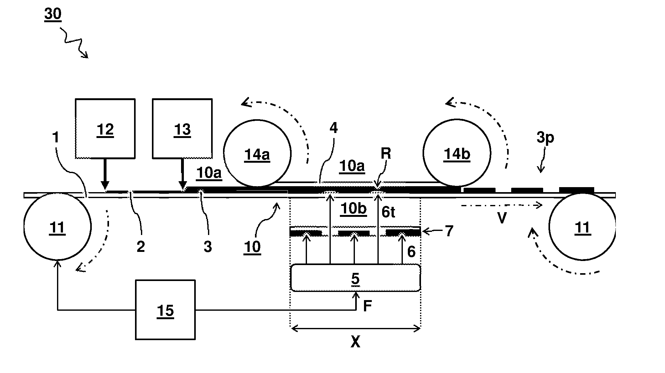
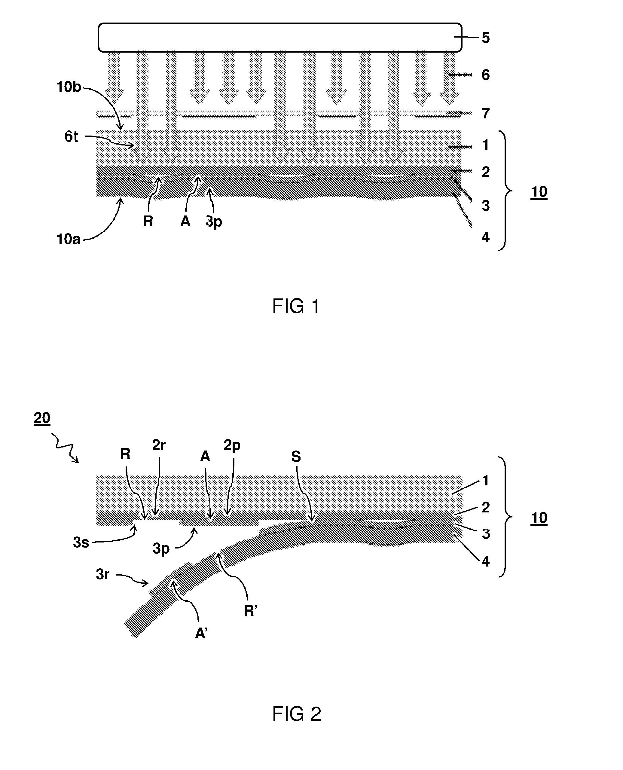
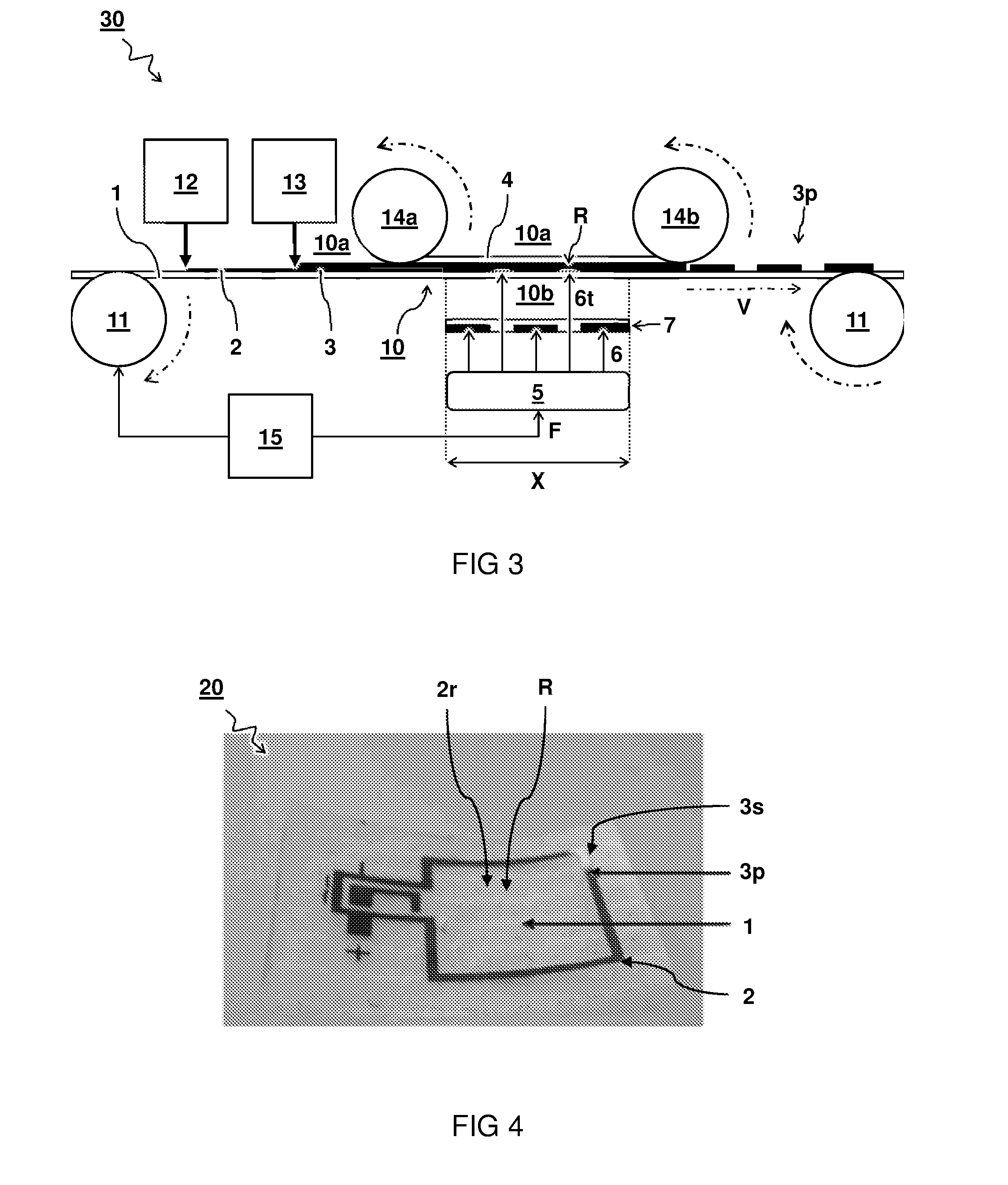
TECHNICAL FIELD AND BACKGROUND[0001]The present disclosure concerns a method and system for forming a patterned structure on a substrate, and the resulting product substrate.[0002]Photolithography and etching processes are often used to pattern thin metal layers on flexible substrates. In photolithography, a polymer can be coated onto the metal film and patterned via UV-light. The metal which is not covered by the polymer is etched away. However, as these techniques are relatively slow, they do not bring the optimal solution for high volume roll-to-roll processing. In printing, conductive inks can be printed in a patterned way via inkjet, (rotary) screen, flexo, gravure, etc. However, as these inks are particle based, a post-treatment step is needed obtain conductivity. In laser ablation, laser systems can be used for ablating and patterning of various materials. However, ablating the metal layer may use a relatively high amount energy.[0003]Accordingly, there is a desire for an imp...

Claims


Application Information

Patent Timeline
IPC IPC(8): H05K3/02G03F7/34H05K1/02B05D3/06H05K3/00
CPCH05K3/027B05D3/06H05K3/0082H05K2201/0108G03F7/343H05K2203/0522H05K2203/0104H05K1/0296G03F7/092G03F7/11G03F7/34G03F7/2002
Inventor HENDRIKS, ROB JACOBSMITS, EDSGER CONSTANT PIETERPERINCHERY, SANDEEP MENONGROEN, PIM
Owner NEDERLANDSE ORG VOOR TOEGEPAST-NATUURWETENSCHAPPELIJK ONDERZOEK (TNO)
Why Eureka
Try Eureka