

Wireless electronic booster, and methods of blasting
a technology of electronic booster and wireless blasting, which is applied in the direction of electric fuze, lighting and heating apparatus, instruments, etc., can solve the problems of increased safety concerns, loss of communication between blasting machines and detonators, and high labor intensity of the process
- Summary
- Abstract
- Description
- Claims
- Application Information
AI Technical Summary
Benefits of technology
Problems solved by technology
Method used
Image

Examples
Embodiment Construction
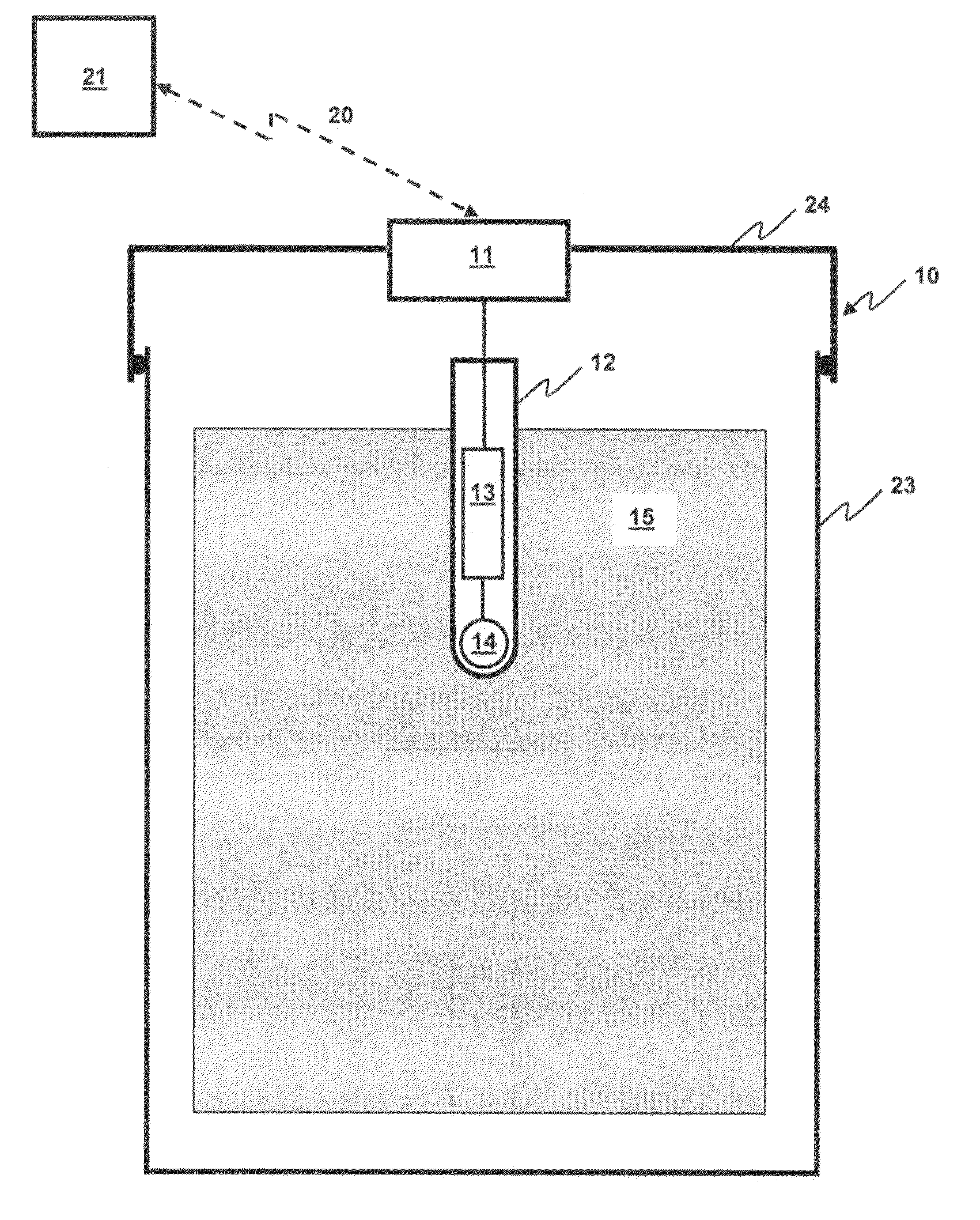
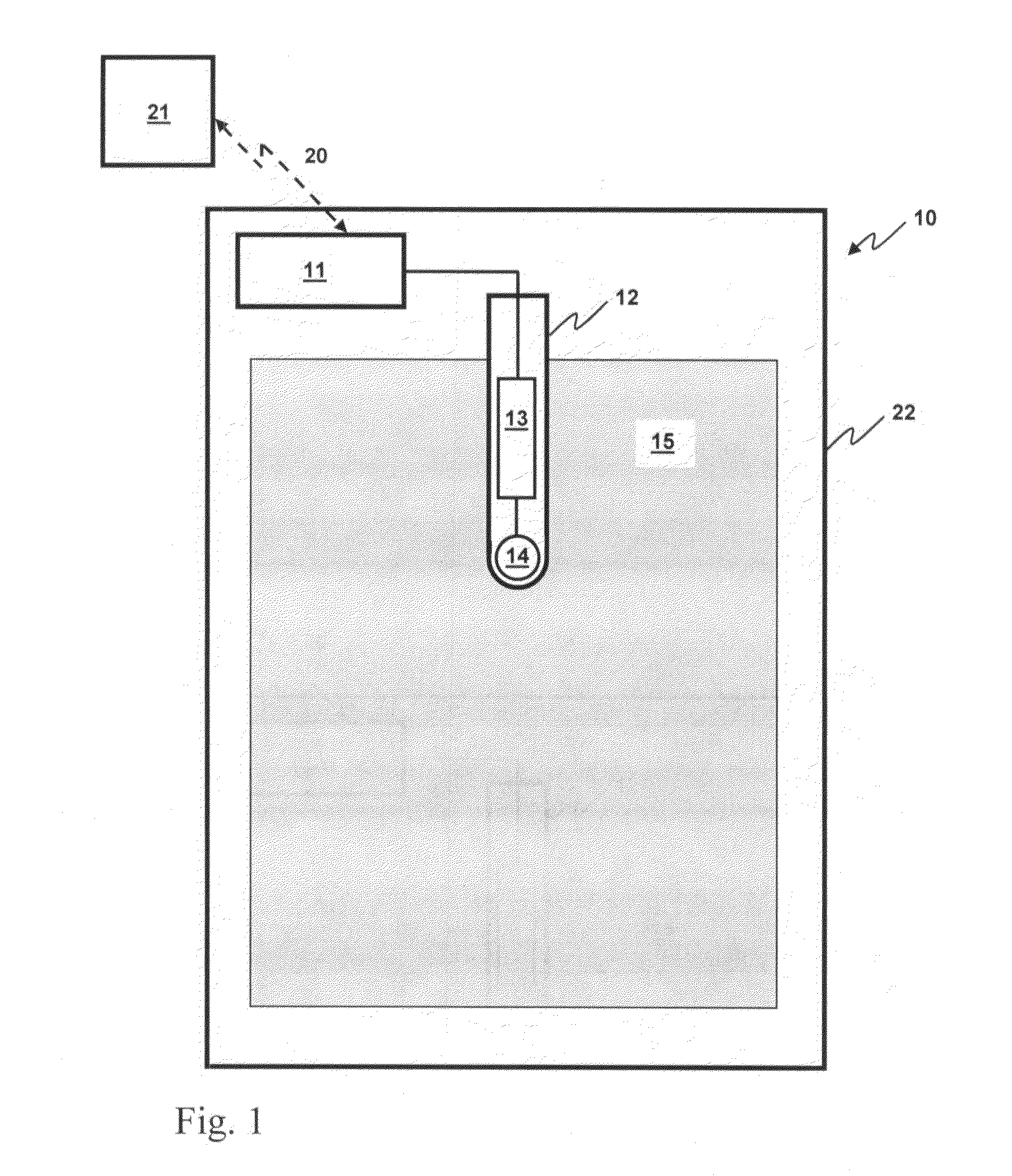
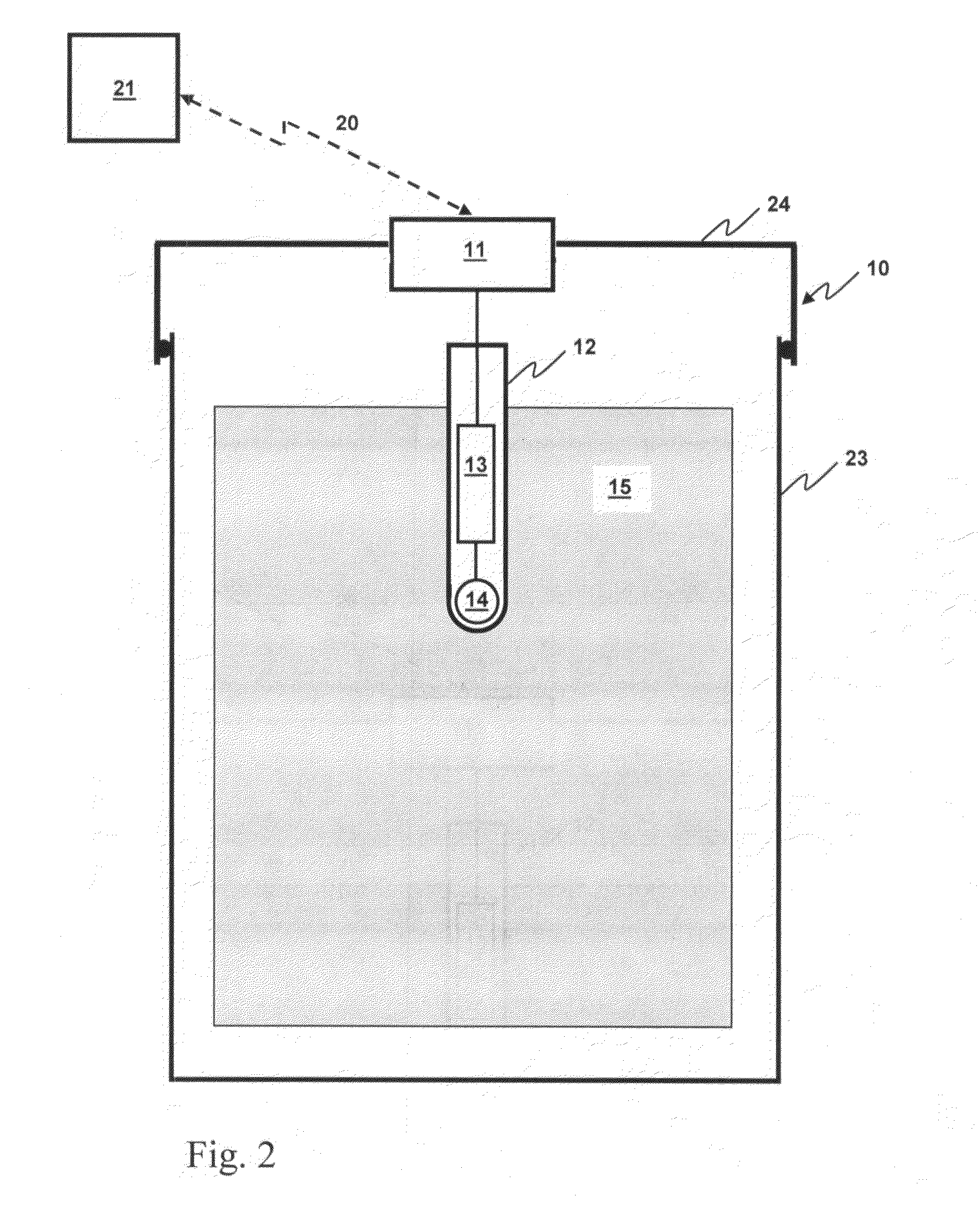
[0059]The inventors have succeeded in the development of wireless electronic boosters for use in mining operations, each wireless booster being capable of wireless communication with a corresponding blasting machine. In preferred embodiments, the wireless electronic boosters may comprise a detonator including a firing circuit and a base charge, an explosive material in operative association with the base charge such that actuation of the base charge causes actuation of the explosive charge. In preferred embodiments, the detonator may include features that substantially avoid the risk of accidental detonator actuation resulting from inappropriate use of operating power for communications. In this way, a blast operator working at a blast site can position boosters, optionally associate the boosters with explosive materials at the blast site, and move away from the blasting site, without the need to establish and lay a multitude of wired connections between the components of the blasti...
PUM
 Abstract
Description
Claims
Application Information