Image matching system and image matching method and program

a matching system and image technology, applied in the field of image matching system, can solve the problems of not being able to detect the rotation angle, unable to obtain the correspondence of images and suitably match images,

Inactive Publication Date: 2010-08-17
SONY CORP
View PDF14 Cites 7 Cited by
  • Summary
  • Abstract
  • Description
  • Claims
  • Application Information

AI Technical Summary

Benefits of technology

[0006]An object of the present invention is to provide an image matching system and an image matching method and program able to

Problems solved by technology

Summarizing the problem to be solved by the invention, the above pattern matching system detecting the amount of parallel movement and the rotation angle, however, cannot obtain correspondence of images and suitably match images when for example the scalings of the registered image and the matching image are different.
Further, the pattern

Method used


Image

  • Image matching system and image matching method and program
  • Image matching system and image matching method and program
  • Image matching system and image matching method and program

Examples


first embodiment

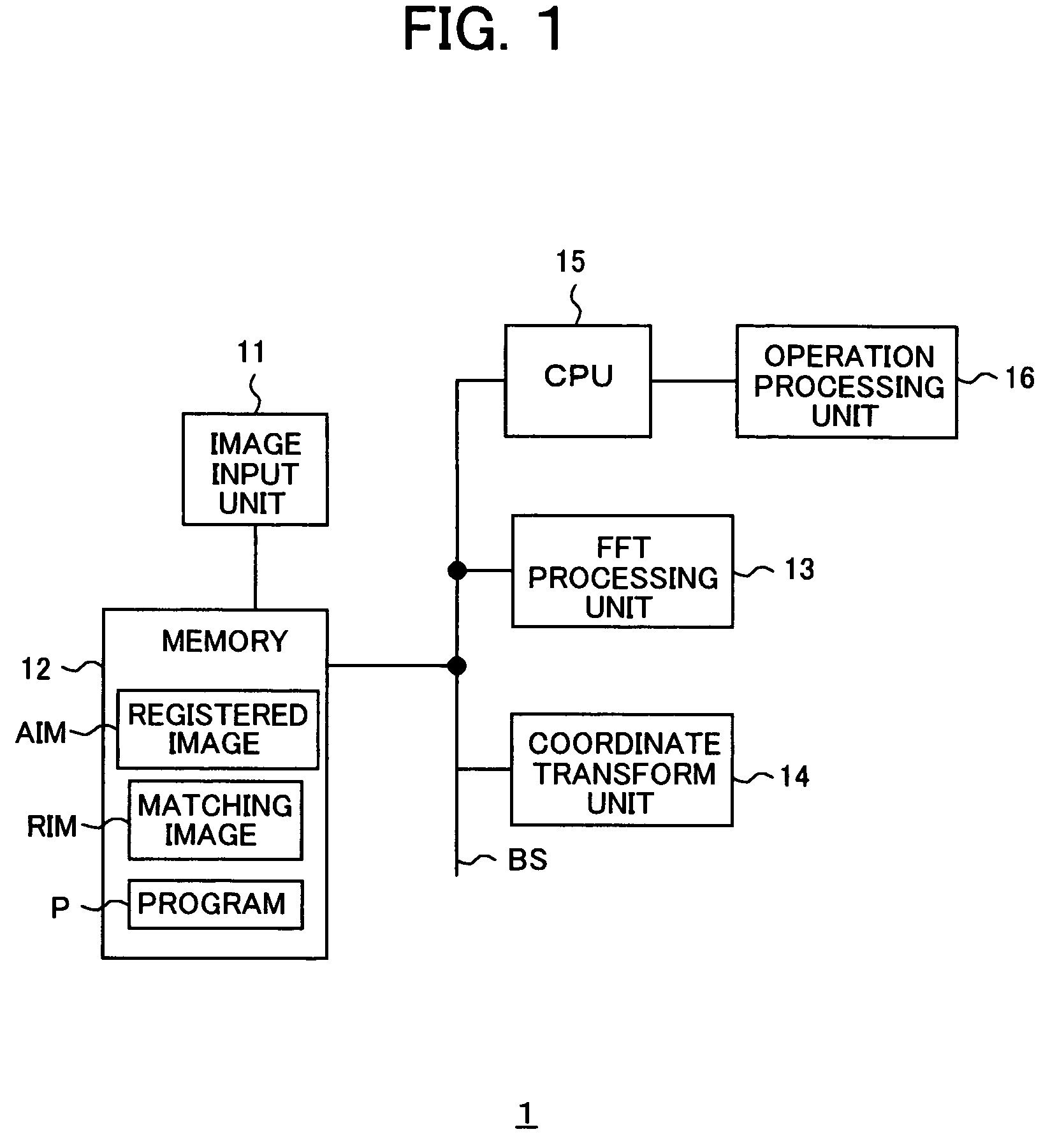
[0037]Preferred embodiments of the present invention will be described in detail below while referring to the attached figures. FIG. 1 is a functional block diagram of an image matching system according to the present invention. The image matching system 1 according to the present embodiment has, for example as shown in FIG. 1, an image input unit 1, a memory 12, an FFT processing unit 13, a coordinate transform unit 14, a CPU 15, and an operation processing unit 16. The image input unit 11, the memory 12, the FFT processing unit 13, the coordinate transform unit 14, and the CPU 15 are connected by a bus BUS. The operation processing unit 16 is connected to the CPU 15.

[0038]The image input unit 11 is an input unit for inputting an image from the outside. For example, the image input unit 11 receives as input a registered image AIM and an image to be compared with the registered image AIM (referred to as a “matching image RIM”) are input. The memory 12 stores the images etc. input fr...

second embodiment

[0100]FIG. 11 is a functional block diagram of an image matching system according to the present invention. An image matching system 1a according to the present embodiment detects positional deviation of the registered image AIM and the matching image RIM, corrects the positional deviation based on the detection result, then extracts the common partial areas of the two images, finds the correlation of each of the extracted common partial areas, and performs matching based on the correlation results.

[0101]The image matching system 1a has the same configuration as the image matching system 1 according to the first embodiment in terms of hardware. The software-like difference between the image matching system 1a and the image matching system 1 according to the first embodiment resides in that, as shown in FIG. 11, a parallel movement detection unit 251, a common partial area extraction unit 252, and a phase only correlation unit 253 are provided. The rest of the components are given th...

third embodiment

[0124]In FIG. 16, the parallel movement detection unit 251 and the parallel movement judgment unit 2512 have the same functions as those of the parallel movement detection unit 2411 and the parallel movement judgment unit 2412 of the image matching system 1b according to the

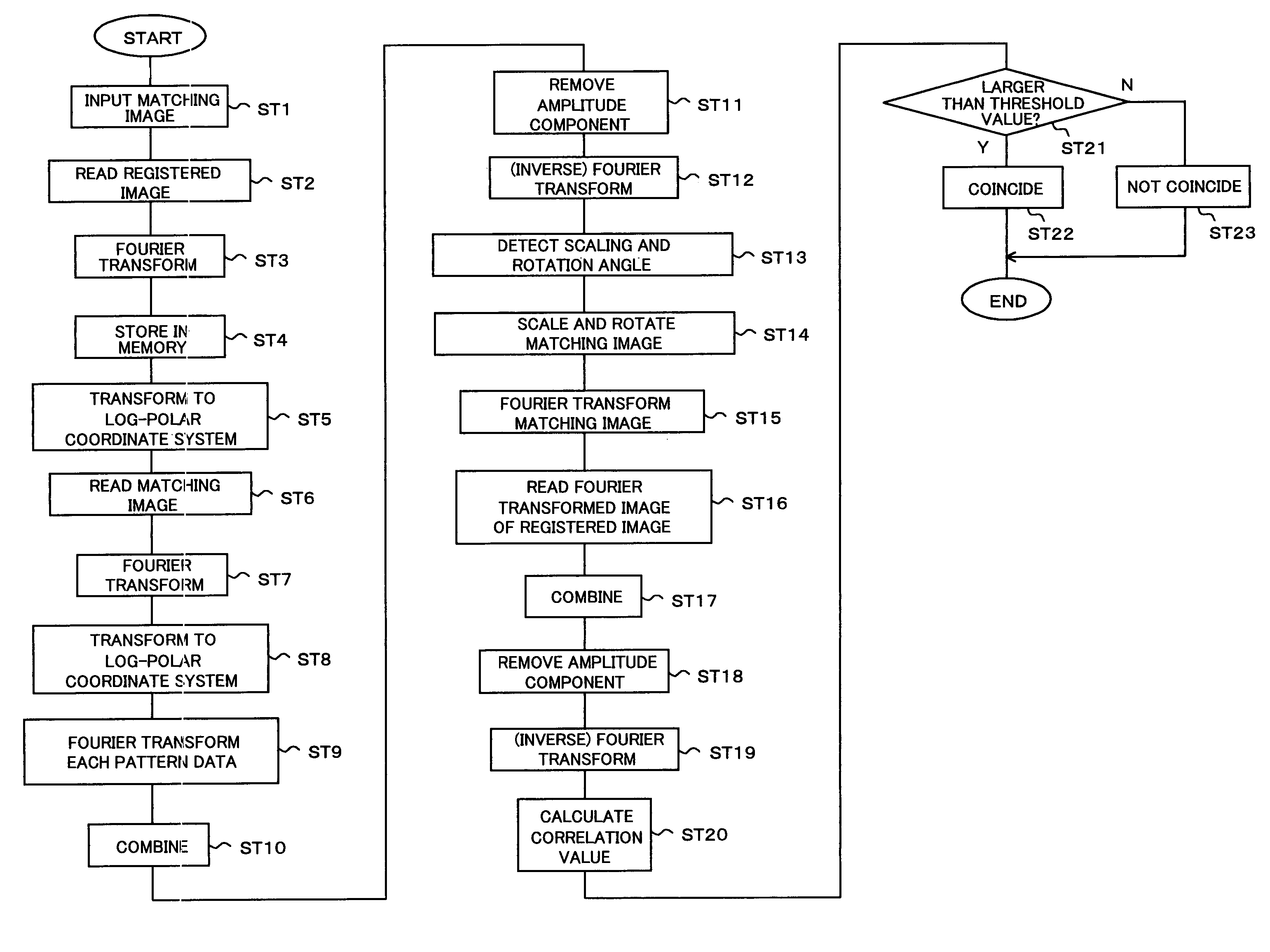
[0125]The parallel movement detection unit 251 detects the amount of parallel movement based on the correlation peak position in the correlation strength image data S23 output from the parallel movement unit 23. The parallel movement judgment unit 2512 judges whether or not the amount of parallel movement is within a predetermined threshold value, in more detail, whether or not the correlation peak position is located in the predetermined window WD based on the amount of parallel movement detected at the parallel movement unit 23, and judges that the two images do not coincide when the amount of parallel movement is larger than the predetermined threshold value.

[0126]Further, in FIG. 16, the common partial area e...


PUM


Abstract

An image matching system, method, and program for matching two images even if there is a difference of parallel movement, rotation angle, and scale between two images. A Fourier-Mellin transform is a Fourier transform and a log-polar coordinate transform to a registered image and a matching image. A phase only correlation unit and scalar information-rotation information generation unit generate correction information including scalar information and rotation information based on correlation strength of the phase information based on the transform result, a correction unit corrects the matching image RIM in accordance with the correction information, a parallel movement unit performs phase only correlation based on the image resulting from the correction processing and the registered image, a correlation value generation unit generates a correlation value based on the correlation image data, and a judgment unit performs judgment concerning the matching based on the correlation value.

Description

BACKGROUND OF THE INVENTION[0001]1. Field of the Invention[0002]The present invention relates to an image matching system for matching images based on image information of for example fingerprint images, still images, and moving images and an image matching method and program.[0003]2. Description of the Related Art[0004]Conventionally, as a method for matching images based on image information, various pattern matching techniques have been known. For example, the technique of detecting an amount of parallel movement and a rotation angle between a registered image and a matching image to be compared with and positioning the two based on the detection results has been proposed. Further, a pattern matching technique for performing a discrete Fourier transform for each of the registered image and the matching image, calculating a degree of correlation based on phase information of each of the obtained pattern data, and matching the images based on the correlation result has been known (...

Claims


Application Information

Patent Timeline
IPC IPC(8): G06K9/62G06T7/00G06V10/75
CPCG06K9/522G06K9/64G06V10/431G06V10/75
Inventor IIZUKA, KEN
Owner SONY CORP
Why Eureka
Try Eureka