Phase Responsive Optical Fiber Sensor

a technology of optical fiber and phase response, applied in the direction of instruments, plant/algae/fungi/lichens ingredients, drug compositions, etc., can solve the problems of reducing or defeating the usefulness of these prior techniques, accumulated polarization effects, and prior art systems that cannot perform consistently, etc., to achieve the effect of reducing the amount of data processing

Inactive Publication Date: 2007-11-01
OPTELLIOS
View PDF8 Cites 34 Cited by
  • Summary
  • Abstract
  • Description
  • Claims
  • Application Information

AI Technical Summary

Benefits of technology

[0035] In the inventive technique described, the signal levels from which phase relationships are derived contain polarization effects. In the inventive technique, polarization variations affect an offset level between the two phase responses. As an offset, the effects are readily subtracted away in data processing. A comparable polarization related effect in prior art interference intensity measurements may produce different intensity responses for the counter-propagating signal directions because of the nonlinear and non-monotonic relationship between phase relationship and the intensity response.
[0036] According to the inventive technique, the at least two independent intensity responses are processed mathematically to produce the phase relationship using multiple independent variable (multi-dimensional) data analysis techniques. At least two independent variables are derived respecting phase and together the variables permit the phase angle itself to be derived. Polarization mismatch affects the phase relationship as an offset. Even polarization state variation over time in many instances is a low frequency effect compared to the time scale of most forms of disturbance to be detected (e.g., acoustic noise), and can be treated much the same as a steady state offset. The time signatures of the changing phase relationships for the counter-propagating directions are substantially identical in shape by this technique. The signatures correlate strongly between the two counter-propagating directions.

Problems solved by technology

There are problems, however, when attempting to use optical fiber waveguides and the like for location detection in this way.
Polarization induced effects can reduce or defeat the usefulness of these prior techniques for discerning the location of the disturbance.
Light waves interfere only when there is some correspondence in the state of polarization, permitting the beams to interfere.
Nevertheless, an accumulated polarization effect arises, particularly over a long distance.
Prior art systems cannot perform consistently, and in some circumstances do not perform at all, because the interfering optical beams vary from time to time between more or less parallel and more or less orthogonal states.
Variable beam interference conditions caused by polarization state changes are recognized as a problem in single light path interferometers, the problem being known as polarization-induced fading.
Polarization induced phase shift, which is caused by the mismatch of the polarization of the interfering beams, is a somewhat different effect from polarization induced fading, but causes measurement problems, because polarization induced phase shift can be difficult to distinguish from other factors.
Such a measurement is difficult and potentially inaccurate, if variations in the two signals cannot be properly matched.
Measurement failure from polarization induced effects is an imminent danger.
The correlation of time varying interference signal signatures for a given disturbance for the two opposite signal paths produces uncertain location measurements due to unpredictable polarization effects.
For all these reasons, the system dependability and accuracy are less than might be desired for security purposes.

Method used


Image

  • Phase Responsive Optical Fiber Sensor
  • Phase Responsive Optical Fiber Sensor
  • Phase Responsive Optical Fiber Sensor

Examples


example 1.1

Polarization Insensitive Beam Combiner

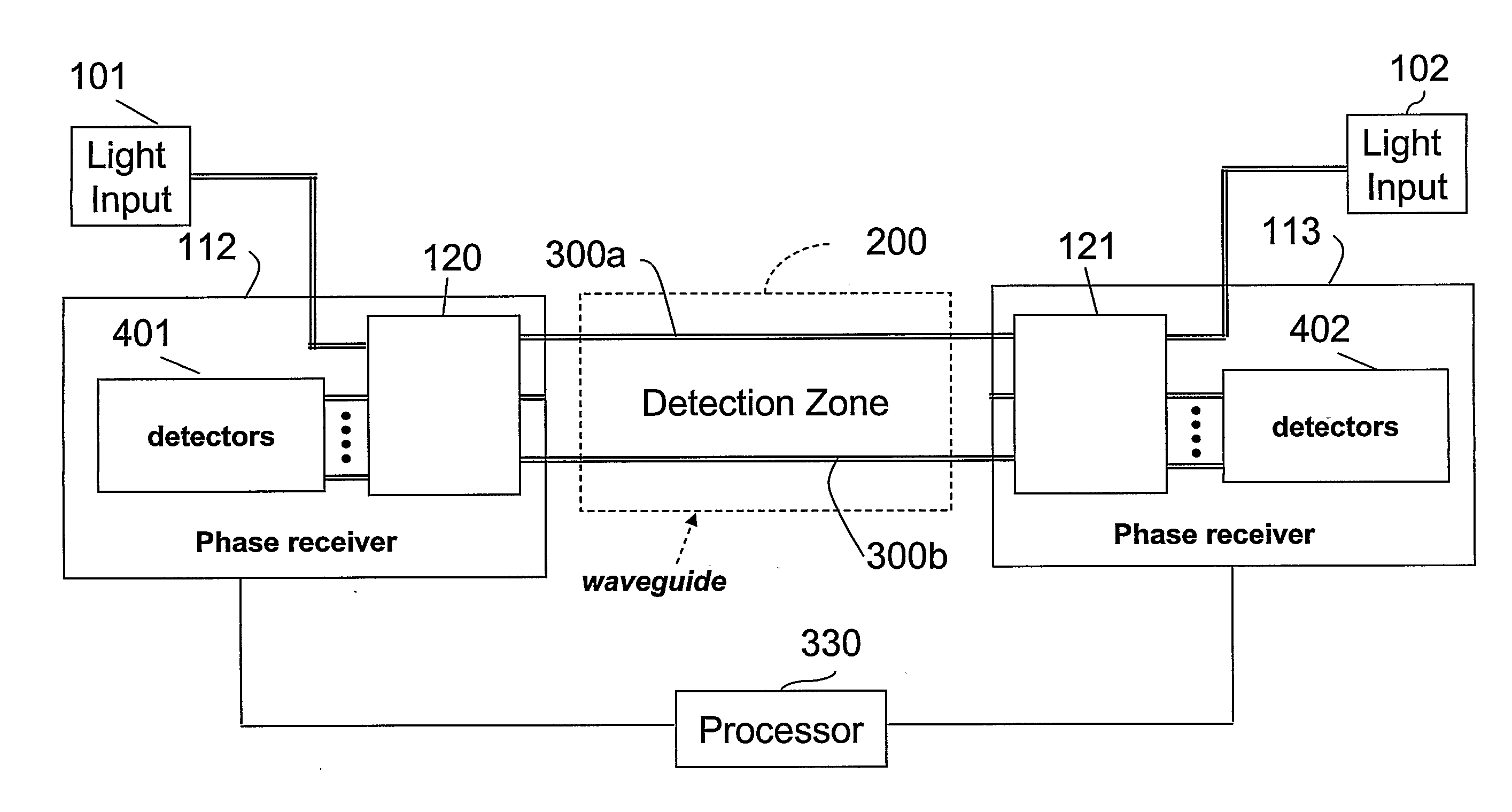
[0121] In this first example, light from the same source is launched into two fibers using a polarization insensitive light splitter. The output light is combined, using a polarization insensitive beam combiner. The combined output light is analyzed using a polarization measurement system (such as a high speed version of PS2300B polarization analyzer available from Optellios, Inc., Langhorne, Pa.) or using another polarization sensitive detector or detection scheme. A detected change of polarization provides information relating to the phase difference between the light signals that travel along the two signal paths for each of the opposite signal directions.

[0122] This approach does not require a particular state of polarization for light signals launched into the fiber(s). Nor is it necessary that the fiber have a particular amount of birefringence. The measurement generally is not influenced by different starting conditions (polarization st...

example 1.2

Polarization Sensitive Beam Combiner

[0137] In this second example, light from the same source is launched into two fibers using a polarization beam splitter, thereby creating two beams. The signal from the same light source can be used to create both counter-propagating beams. The light beams pass through the detection zone and are then combined, using a polarization beam combiner so as to analyze the orthogonal components of the beams in the two fibers. The combined signal is analyzed using a polarimeter or other polarization sensitive detection scheme. The change of polarization provides the information about the phase difference between the beams that travel along the two paths.

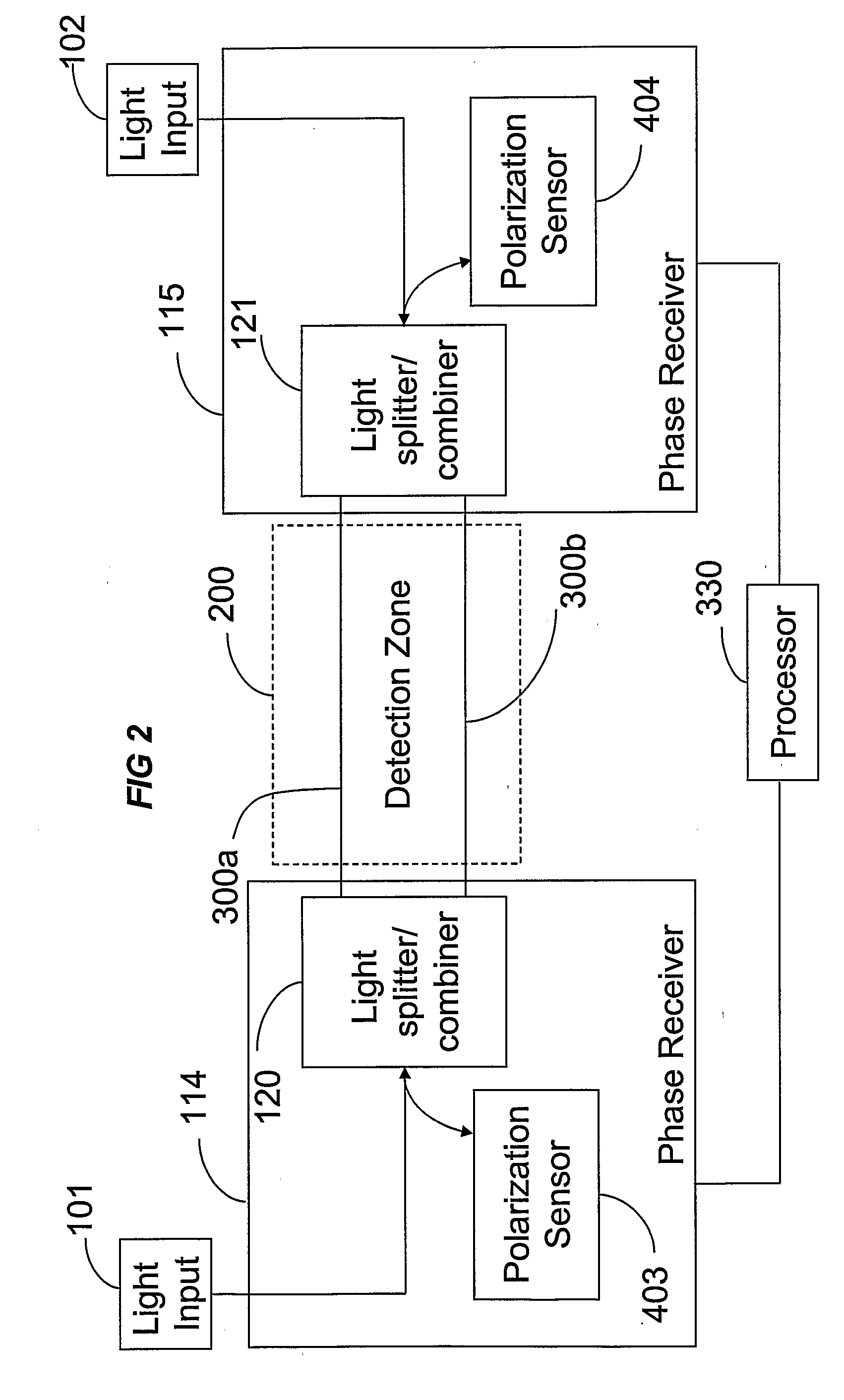
[0138] A schematic example demonstrating phase detection based on polarization change is shown in FIG. 8. Light is injected into two paths 300a and 300b by operation of a beam splitter 122 (element A). In the illustrated example, the beam splitter is a polarization beam splitter. Both beams are recombine...


PUM


Abstract

The location of a physical disturbance along an optical waveguide is determined by measuring different propagation times for the resulting phase variation to propagate to phase responsive receivers at ends of bidirectional signal paths. Each receiver can have a coupler that functions as a beam combiner and as a beam splitter inserting the opposite signal. On each receiving end, the coupler provides one or more detectors with signals from which phase related independent variable values are taken, processed and mapped to phase angles. Relative phase angle versus time is derived for each opposite signal pair and correlated at a time difference, i.e., a difference in propagation time from which the location of the disturbance is resolved. Polarization sensitive and polarization insensitive examples are discussed with various optical fiber arrangements.

Description

BACKGROUND OF THE INVENTION [0001] 1. Field of the Invention [0002] The invention concerns techniques for detecting and accurately determining the location of a physical disturbance. Input signals are coupled in two opposite directions along a waveguide, through multiple signal paths, at least one such path traversing a detection zone. The waveguide, for example, can consist of one or more optical fibers. Multiple signal paths can be provided by distinct signals traveling in different fibers, and / or multiple signal paths can be provided using different modes of signal propagation in one or more of the same fibers. [0003] In exemplary applications of the inventive techniques, optical fibers are routed around a security perimeter, along or across a road or path, coextensively with a power or signal transmission line, on or near a pipeline, etc. A disturbance such as sound or vibration from nearby activity changes the propagation conditions of the light signals carried in the multiple ...

Claims


Application Information

Patent Timeline
Patent Type & Authority Applications(United States)
IPC IPC(8): G02B6/10
CPCG01M11/39G02B6/2766H04B10/0771G08B13/186G08B13/2491G08B13/184A61K8/25A61K8/26A61K8/27A61K8/368A61K8/922A61K8/9711A61K8/9789A61K8/9794A61K9/0014A61K36/185A61K36/54A61K36/63A61K36/736A61K36/82A61K36/886A61K36/889A61K36/899A61K2800/31A61K2800/522A61P17/00A61P35/00A61Q19/00A61Q19/001A61K2300/00
Inventor PATEL, JAYANTILAL S.ZHUANG, ZHIZHONGZADOROZHNY, YURI
Owner OPTELLIOS
Why Eureka
Try Eureka