
Cooking apparatus

a technology of cooking apparatus and cooking chamber, which is applied in the direction of dielectric heating, hot plate heating arrangement, electrical heating fuel, etc., can solve the problems of severe energy waste in conventional ovens, long cooking time, and small amount of food that can be cooked in one cooking process, so as to improve energy efficiency and quick and easy cooking of objects

Active Publication Date: 2010-08-24
LG ELECTRONICS INC
View PDF8 Cites 37 Cited by
  • Summary
  • Abstract
  • Description
  • Claims
  • Application Information

AI Technical Summary

Benefits of technology

[0014]An object of the present invention is to provide a cooking apparatus capable of rapidly and easily cooking an object to be cooked.
[0015]Another object of the present invention is to provide a cooking apparatus capable of achieving an enhancement in energy efficiency.
[0022]The socket may be provided with a socket cover configured to prevent foreign matter from entering the socket when the plug is not coupled to the socket.

Problems solved by technology

First, there is inconvenience in that it is necessary to turn over food when the food is to be broiled at opposite surfaces thereof, because the heater used in the conventional oven can supply heat only to the upper surface of the food. For this reason, there is a problem in that the cooking time becomes long.
Second, when food to be cooked is broiled by the heater included in the conventional oven, there is a problem in that the amount of food that can be cooked in one cooking process is small because the cooking of the food can be carried out only on the upper surface of a rack installed in the oven.
Third, the conventional oven involves severe energy wasting because it is necessary to heat the entire portion of the cavity even when only a small amount of food is cooked.

Method used


Image

  • Cooking apparatus
  • Cooking apparatus
  • Cooking apparatus

Examples


Embodiment Construction

[0035]Reference will now be made in detail to the preferred embodiments of the present invention, examples of which are illustrated in the accompanying drawings.

[0036]Hereinafter, a cooking apparatus according to the present invention and a heating device included in the cooking apparatus will be described in detail.

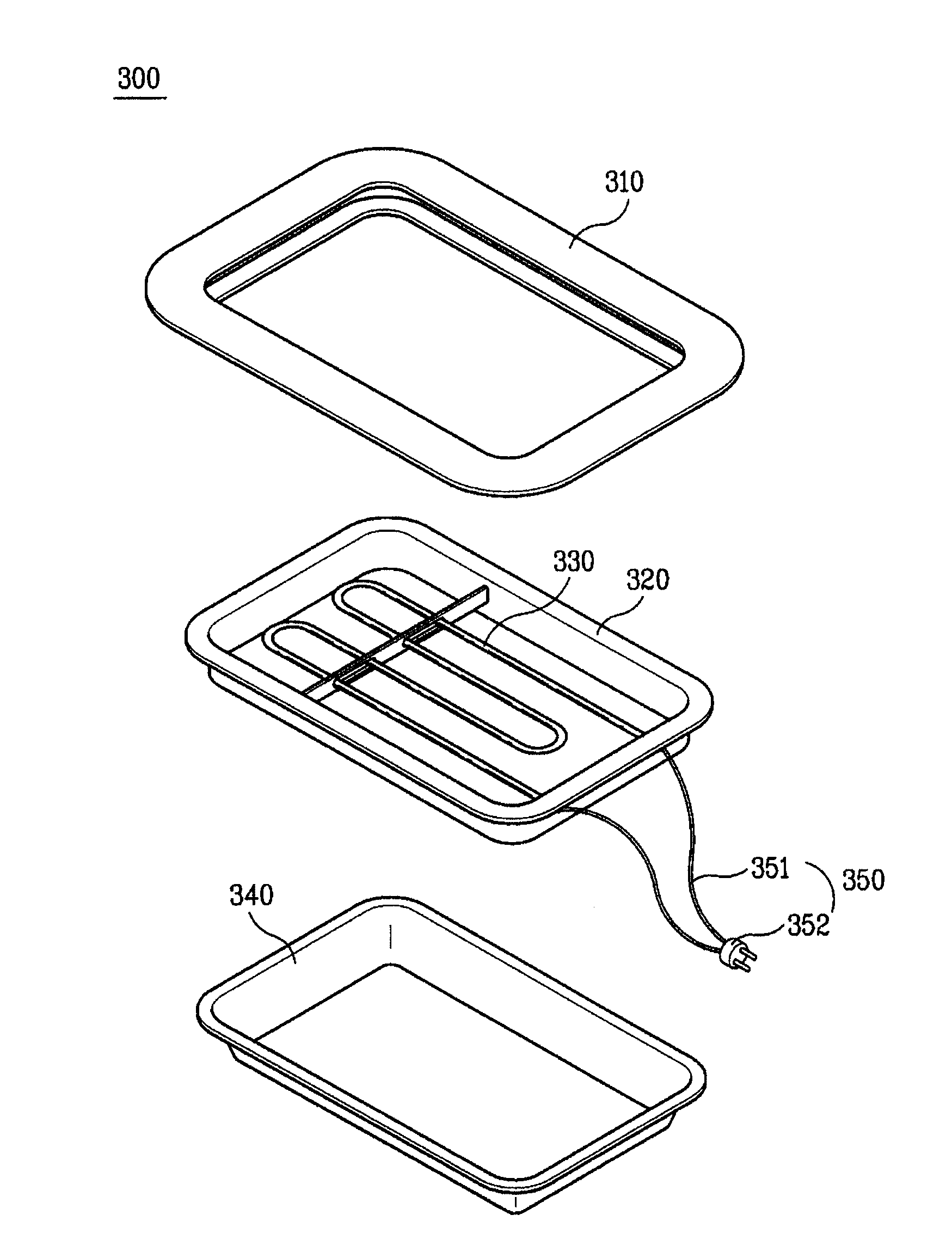
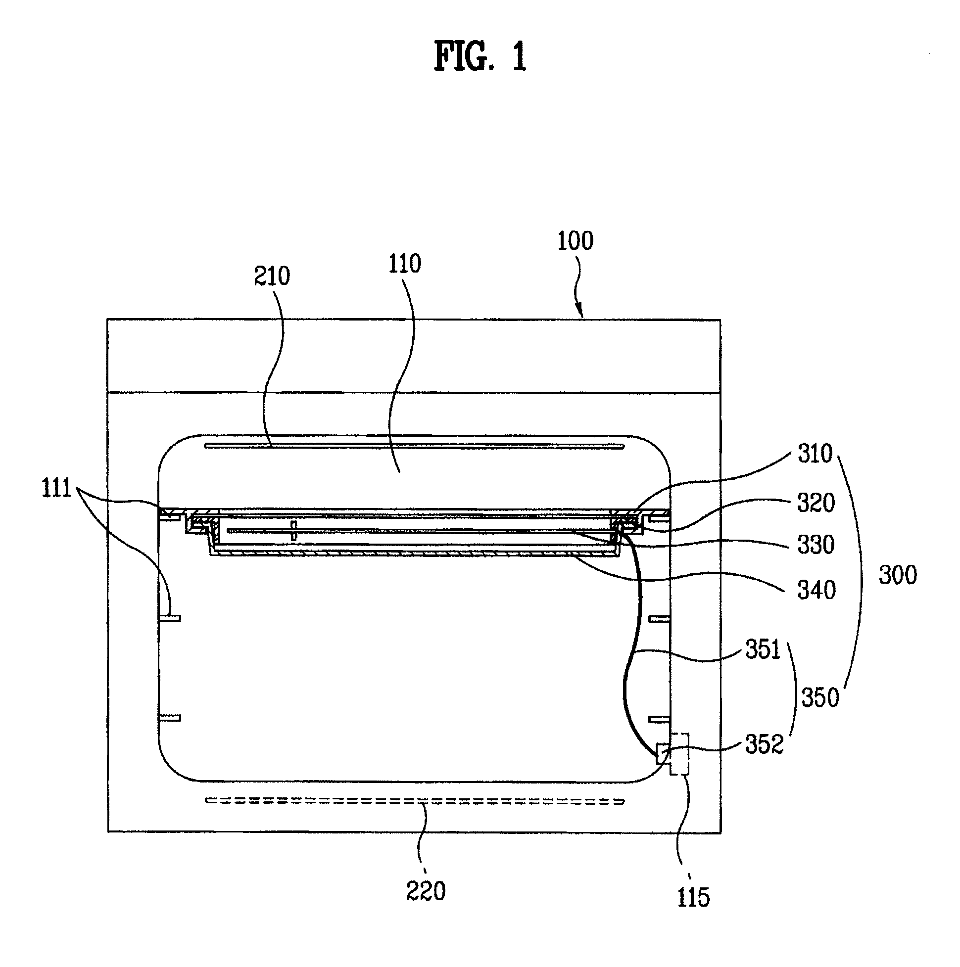
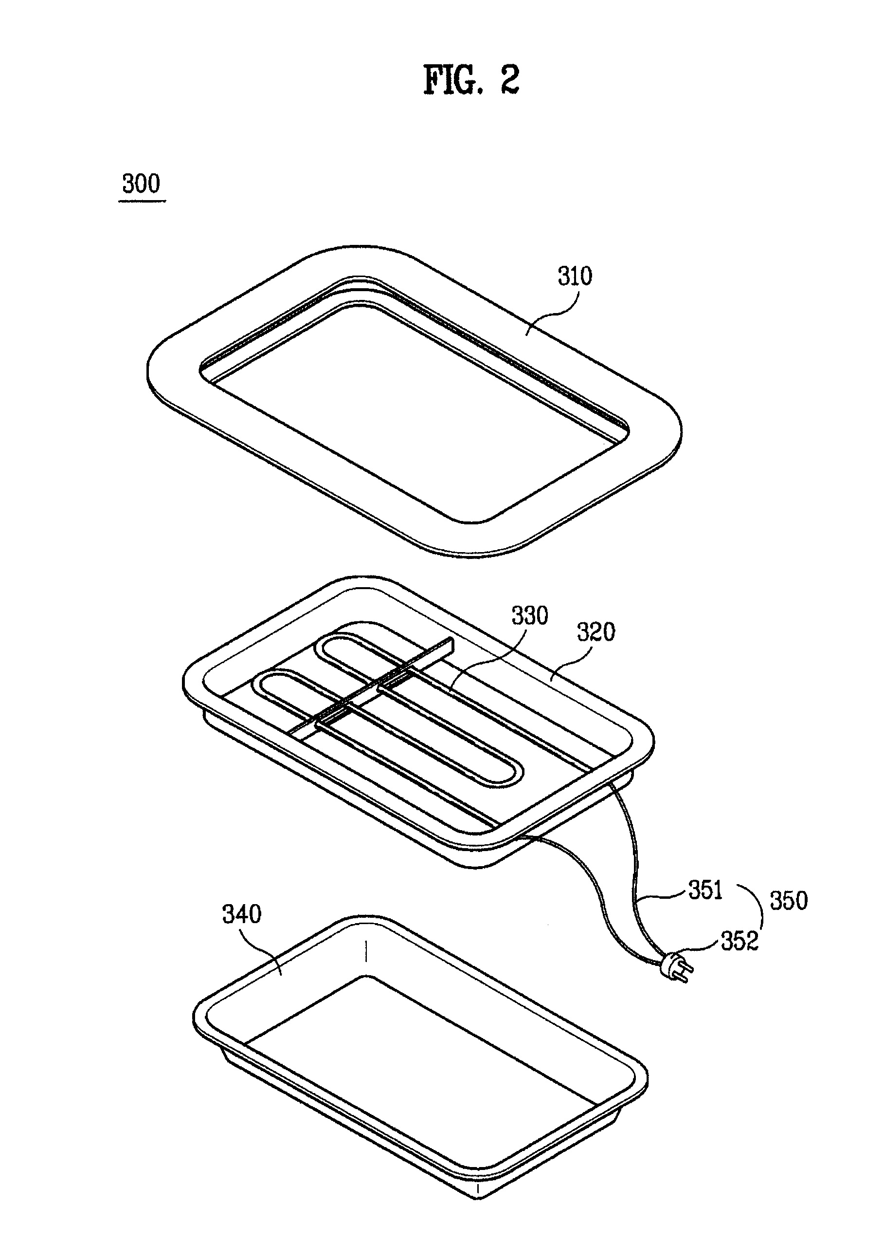
[0037]The cooking apparatus includes a body or housing 100 providing a cavity or chamber 110 as a space in which an object is cooked, a broiling heater 210 mounted to the inner top surface of the cavity or chamber 110, and a baking heater 220 mounted to an inner bottom surface of the cavity or chamber 110. The cooking apparatus also includes a heating device 300 detachably installed in the cavity 110, and a door (not shown) for opening and closing the cavity 110 of the body or housing 100.

[0038]The body 100 defines the appearance of the cooking apparatus in any suitable form, such as that of a substantially rectangular case. The cavity 110 as the space in which the objec...


PUM


Abstract

A cooking apparatus is disclosed. The cooking apparatus includes a housing having a cooking chamber and a heating unit. The heating unit includes a partition plate detachably installed in the chamber, the partition plate partitioning the chamber into sub-chambers, and a heater configured to heat at least one of the sub-chambers.

Description

[0001]This application claims the benefit of Korean Patent Application No. 10-2006-0040737, filed on May 4, 2006, which is hereby incorporated by reference as if fully set forth herein.BACKGROUND OF THE INVENTION[0002]1. Field of the Invention[0003]The present invention relates to a cooking apparatus, and more particularly, to a cooking apparatus capable of reducing the cooking time of food.[0004]2. Discussion of the Related Art[0005]In general, there are a variety of types of cooking appliances, such as ovens, microwave ovens, and other suitable types of ovens. Microwave ovens are provided with only a magnetron, or both with a magnetron and a heater for cooking food. An oven is a cooking appliance designed for cooking food enclosed therein with dry heat. A heat source for supplying the heat to the food may be an electric heater or a gas heater.[0006]In general, ovens include a cavity providing a space for receiving food to be cooked, a door for opening or closing the cavity, and a ...

Claims


Application Information

Patent Timeline
Patent Type & Authority Patents(United States)
IPC IPC(8): A21B1/00A47J37/06
CPCF24C7/06F24C15/166H05B3/68
Inventor NAM, YOUNG-SOKNAM, HYEUN SIKLEE, YONG SOOCHO, SEONG HO
Owner LG ELECTRONICS INC
Learn More