Turbulence reduction around magnus rotors

a rotor and magnus technology, applied in the direction of machines/engines, mechanical equipment, electric generator control, etc., can solve the problems of increasing the drag/lift coefficient as much as possible, the same angular velocity as the rotor was ineffective in reducing the induced drag on the end surface of the rotor, and the wind turbine efficiency is severely limited

Inactive Publication Date: 2010-08-24
NEWMAN EDWIN
View PDF9 Cites 8 Cited by
  • Summary
  • Abstract
  • Description
  • Claims
  • Application Information

AI Technical Summary

Benefits of technology

[0014]Magnus Rotors are mounted atop a pole with their driving motors. This pole is divided into two vertical poles. On the upper ends of these two poles a long shaft is suspended between them. This shaft serves as a hub around which are mounted a number of Magnus rotors. A gear mechanism transmits the energy of the rotating shaft to an electric generator. Thus the mass of the supporting structure is eliminated as a source of turbulence around the Magnus Rotors.

Problems solved by technology

But wind turbine efficiency is severely limited since a great deal of the incoming wind energy blows through the propeller arc without affecting performance.
The general problem is to increase as much as possible the coefficient of drag / lift so more power can be produced over the same frontal area of whatever shaped energy collector is placed in the wind stream.
1. end plates fixedly attached to the rotor and larger in diameter than the Rotor itself and were spun at the same angular velocity as the Rotor were ineffective in reducing induced drag on the end surfaces of the Rotor.
2. Designing a Rotor which is made to spin rapidly and at the same time be made to whirl rapidly around a central hub produces singular drag problems. These and other problems were recognised in the Holland experiments and are addressed in the present invention.

Method used


Image

  • Turbulence reduction around magnus rotors
  • Turbulence reduction around magnus rotors

Examples


Embodiment Construction

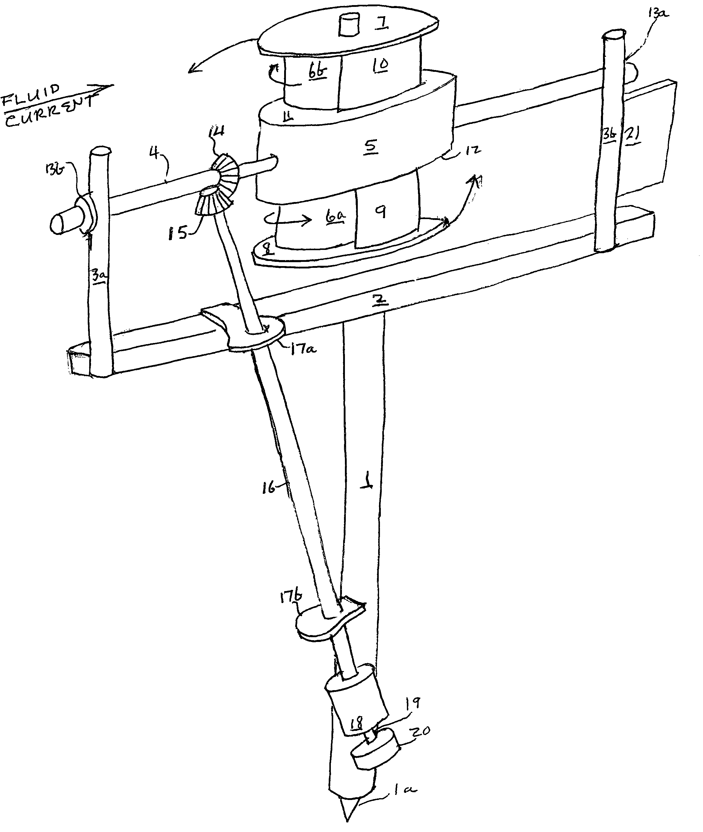
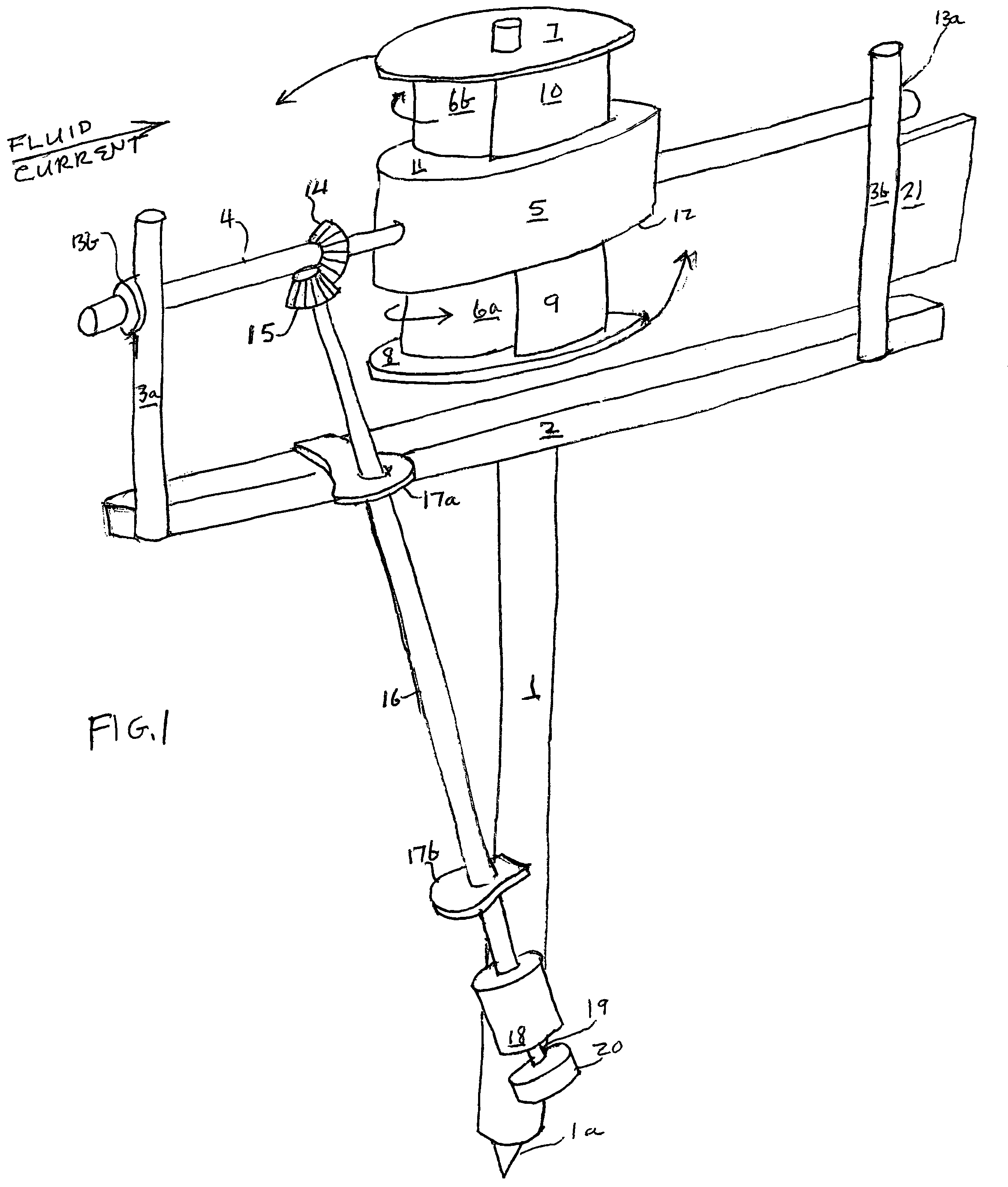
[0017]Fixedly attached to pivot 1a is vertical pole 1, Horizontal support 2 is a long square pipe fixedly attached to the top of vertical pole 1. Shaft 4 is supported at the tops of vertical supports 3a,3b by ball bearing mounts 13a,13b. These vertical supports 13a,13b are fixedly attached to either end of horizontal support 2.

[0018]Shaft 4 is therefor parallel to support 2. Fixedly attached to shaft 4 are attached Magnus Rotors 6a,6b driven by motors in the manner of prior art. Fixedly attached to vertical support 3b is weathervane 21. Also fixedly attached to shaft 4 are motor housing 5, endplates 7,8,11,12, and rotor tails 9,10 as taught by Holland in the prior art. These attachments to shaft 4 are revolved with shaft 4. Also mounted fixedly on shaft 4 is bevel gear 14. Meshed with bevel gear 14 is a second bevel gear 15. Shaft 16 is operatively attached to bevel gear 15 on one end and on its other end is operatively attached to speed changer 18 which is bolted to vertical pole 1...


PUM


Abstract

A fluid energy conversion system using a Magnus Rotor to generate force and electrical power from passing fluid such as wind. A Magnus Rotor is mounted atop support structure which is far enough away from the surface of the Rotor to minimize fluid turbulence around the peripheral surfaces of the Rotor. The Rotor is mounted on a long horizontal shaft supported by a divided pole on either end. This divided pole is mounted on a pivot so the Magnus Rotor will be faced to the oncoming fluid by a weathervane. Minimizing fluid turbulence can result in greater power production.

Description

[0001]This invention is a Continuation-In-Part of patent application Ser. No. 11 / 985,200 filed Nov. 13, 2007.A. BACKGROUND OF THE INVENTION[0002]1. Field of the Invention[0003]This invention relates to fluid energy conversion systems, and more specifically one powered with Magnus Rotors.[0004]2. Description of the Prior Art[0005]Air pressure at the earth's surface is 14.7 lbs. / sq. inch. This is about a metric ton / sq. ft. So a cubic foot of air weighs about a metric ton. If this cubic ft. of air is made to move 10 miles / hour the power developed is over 56 horsepower. So theoretically wind energy can supply all man's energy needs. There has been some progress in extracting this energy. In order to do so at 100% efficiency a perfect vacuum must be somehow operatively connected with normal air pressure. Airfoils are used to cause a mild pressure difference which is enough to lift aircraft and, in the form of a propeller, to spin wind turbines to produce electrical energy. But wind turbi...

Claims


Application Information

Patent Timeline
Patent Type & Authority Patents(United States)
IPC IPC(8): F03D9/00F01D1/36
CPCF03D1/0616F03D5/00Y02E10/70Y02E10/721Y02E10/72F03D1/0601
Inventor NEWMAN, EDWIN
Owner NEWMAN EDWIN
Why Eureka
Try Eureka