Method for reducing network bandwidth by delaying shadow ray generation

a network bandwidth and shadow ray technology, applied in the field of image processing, can solve the problems of rasterization suffering from some drawbacks, modern monitors display images, and use relatively low amounts of computational power

Active Publication Date: 2010-08-24
ACTIVISION PUBLISHING
View PDF6 Cites 126 Cited by
  • Summary
  • Abstract
  • Description
  • Claims
  • Application Information

AI Technical Summary

Problems solved by technology

One limitation of rendering realistic images is that modern monitors display images through the use of pixels.
Rasterization is effective at rendering graphics quickly and using relatively low amounts of computational power; however, rasterization suffers from some drawbacks.
For example, rasterization often suffers from a lack of realism because it is not based on the physical properties of light, rather rasterization is based on the shape of three-dimensional geometric objects in a scene projected onto a two dimensional plane.
Furthermore, the computational power required to render a scene with rasterization scales directly with an increase in the complexity of the scene to be rendered.
As image processing becomes more realistic, rendered scenes also become more complex.
Therefore, rasterization suffers as image processing evolves, because rasterization scales directly with complexity.
Furthermore, ray tracing also handles increases in scene complexity better than rasterization as scenes become more complex.
This is due to the fact that the same number of rays may be cast into a scene, even if the scene becomes more complex.
One major drawback of ray tracing is the large number of calculations, and thus processing power, required to render scenes.
This leads to problems when fast rendering is needed.
Due to the increased computational requirements for ray tracing it is difficult to render animation quickly enough to seem realistic (realistic animation is approximately twenty to twenty-four frames per second).

Method used


Image

  • Method for reducing network bandwidth by delaying shadow ray generation
  • Method for reducing network bandwidth by delaying shadow ray generation
  • Method for reducing network bandwidth by delaying shadow ray generation

Examples


Embodiment Construction

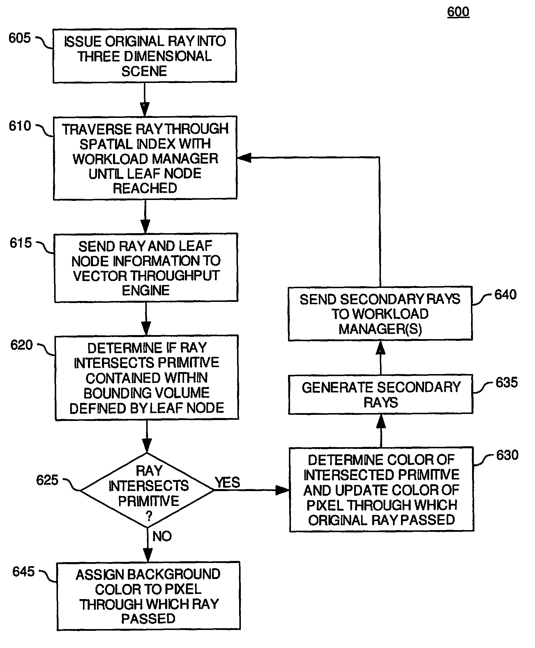
[0027]The present invention provides methods and apparatus in a ray tracing image processing system for generating secondary rays in response to a ray-primitive intersection. According to embodiments of the invention, a first processing element in the image processing system may generate a portion of secondary rays in response to a ray-primitive intersection. Furthermore, a second processing element in the image processing system may generate second portion of secondary rays in response to the ray-primitive intersection. According to one embodiment of the invention, the first processing element may generate reflected and refracted rays in response to a ray-primitive intersection, and the second processing element may generate shadow rays in response to the ray-primitive intersection. The first processing element may send the ray-primitive intersection point to the second processing element to indicate that the second processing element may generate the shadow rays. By generating a p...


PUM


Abstract

The present invention provides methods and apparatus in a ray tracing image processing system to reduce the amount of information passed between processing elements. According to embodiments of the invention, in response to a ray-primitive intersection, a first processing element in the image processing system may generate a portion of secondary rays and a second processing element may generate a second portion of secondary rays. The first processing element may generate reflected and refracted rays and the second processing element may generate shadow rays. The first processing element may send a ray-primitive intersection point to the second processing element so that the second processing element may generate the shadow rays. By only sending the intersection point to the second processing element, in contrast to sending a plurality of shadow rays, the amount of information communicated between the two processing elements may be reduced.

Description

BACKGROUND OF THE INVENTION[0001]1. Field of the Invention[0002]Embodiments of the invention generally relate to the field of image processing.[0003]2. Description of the Related Art[0004]The process of rendering two-dimensional images from three-dimensional scenes is commonly referred to as image processing. As the modern computer industry evolves image processing evolves as well. One particular goal in the evolution of image processing is to make two-dimensional simulations or renditions of three-dimensional scenes as realistic as possible. One limitation of rendering realistic images is that modern monitors display images through the use of pixels.[0005]A pixel is the smallest area of space which can be illuminated on a monitor. Most modern computer monitors will use a combination of hundreds of thousands or millions of pixels to compose the entire display or rendered scene. The individual pixels are arranged in a grid pattern and collectively cover the entire viewing area of the...

Claims


Application Information

Patent Timeline
Patent Type & Authority Patents(United States)
IPC IPC(8): G06T15/50
CPCG06T15/06
Inventor SHEARER, ROBERT ALLEN
Owner ACTIVISION PUBLISHING
Why Eureka
Try Eureka