Deployable telescope having a thin-film mirror and metering structure

a technology of metering structure and telescope, which is applied in the field of optical systems, can solve the problems of increasing the difficulty of deployment of ever larger telescopes, and affecting the operation of the telescop

Inactive Publication Date: 2010-08-24
NAT TECH & ENG SOLUTIONS OF SANDIA LLC
View PDF9 Cites 16 Cited by
  • Summary
  • Abstract
  • Description
  • Claims
  • Application Information

AI Technical Summary

Benefits of technology

[0009]Compared to previous systems, the deployable thin-film minor telescope in various embodiments may overcome many technical obstacles, including one or more of the following: how to package a large sheet of thin-film mirror material without folds or wrinkles; how to protect an optical surface from scratches without having to eject a protective cover; how to deploy a large sheet of minor material in a predictable, orderly fashion; how to position a large sheet of mirror material accurately without over-redundant constraints; how to re-package a large sheet of mirror material remotely and retract the mechanism; and how to extend a secondary mirror without a low-order torsional bending mode.

Problems solved by technology

A challenge for designers of telescopes for space applications is how to create larger telescopes that may be lifted into orbit.
This limitation is due, in part, to the size restrictions for payloads of the vehicles that are launched into space, as payload space in these vehicles is limited in both size and weight.
Although certain large structures have been deployed into space to serve with good success, e.g., as radio antennas and reflectors, ever larger telescopes are generally more difficult to deploy due to the requirement for perfect shape and positioning of the optical surface.
These segmented mirrors are relatively large and heavy due to their structure, so these previous solutions do not take advantage of certain newer technologies, such as thin-film mirrors.

Method used


Image

  • Deployable telescope having a thin-film mirror and metering structure
  • Deployable telescope having a thin-film mirror and metering structure
  • Deployable telescope having a thin-film mirror and metering structure

Examples


Embodiment Construction

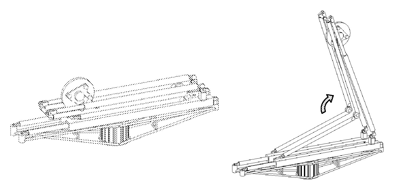
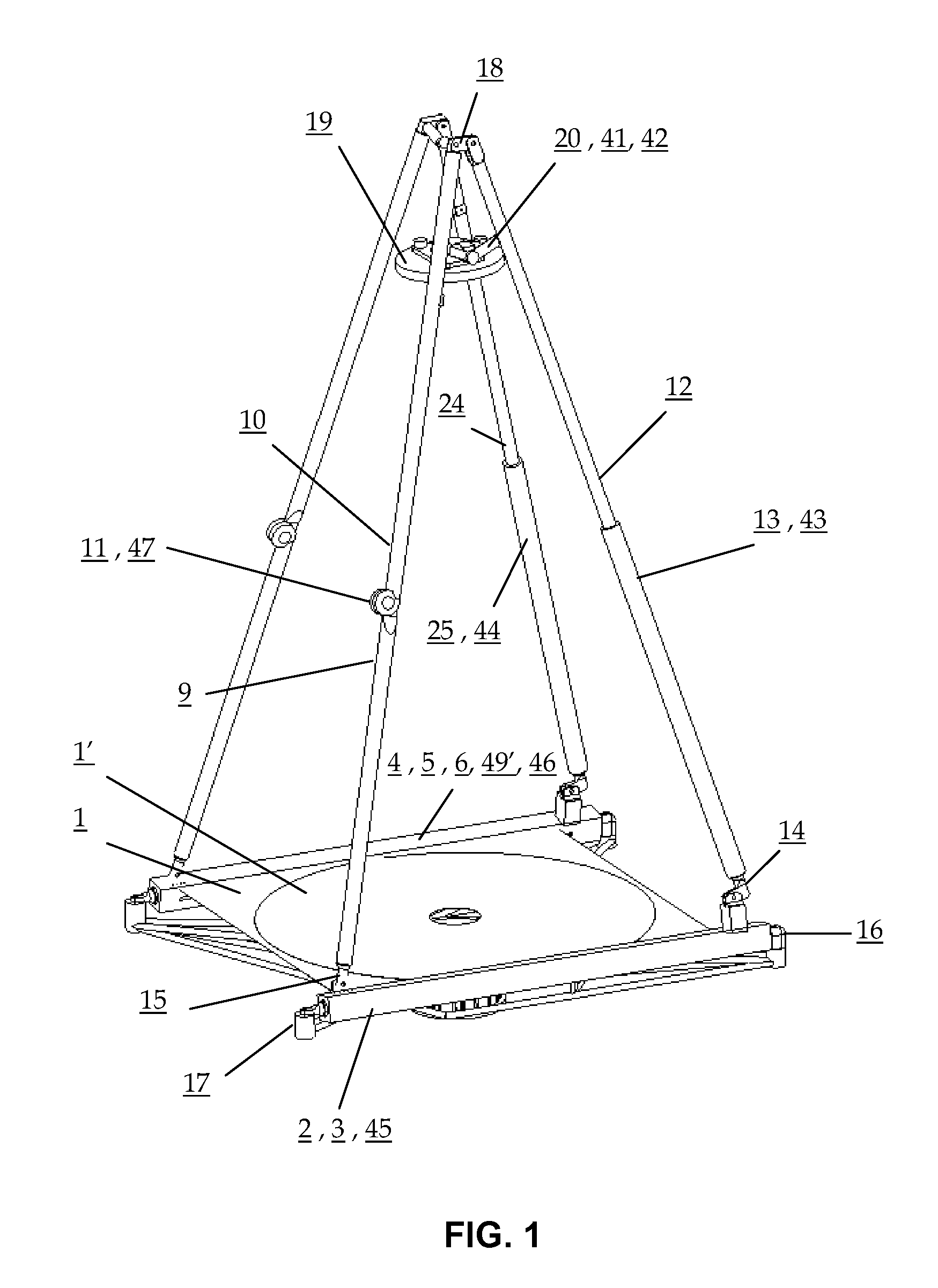
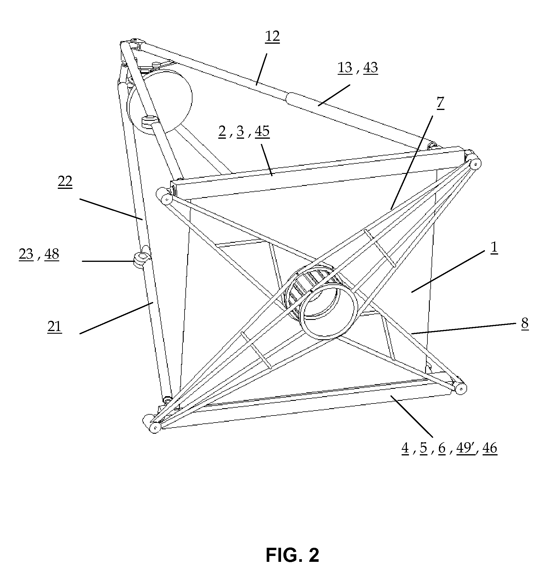
[0022]In various embodiments of the present invention, an optical assembly includes primary and secondary mirrors attached to deployable structures to form a folding telescope. In one embodiment, this optical assembly forms a Cassegrain telescope. In another embodiment, this optical assembly forms a Newtonian telescope. FIGS. 1 and 2 are isometric views of a folding telescope in its deployed state, in accordance with one embodiment, and FIG. 3 illustrates the same folding telescope in its folded or retracted state. FIGS. 5 and 6 are isometric views of a folding telescope in its deployed state, in accordance with another embodiment. As used herein, the term “deployed” refers to the system's ability to expand in size and change shape from a contracted state for storage to an expanded state for operation—as opposed to the other meaning of the term that refers to sending something away on a mission.

[0023]As illustrated in FIGS. 1, 2, 4, 5 and 6, the telescope comprises a primary minor 1...


PUM


Abstract

A deployable thin-film mirror telescope comprises a base structure and a metering structure. The base structure houses a thin-film mirror, which can be rolled for stowage and unrolled for deployment. The metering structure is coupled to the base structure and can be folded for stowage and unfolded for deployment. In the deployed state, the unrolled thin-film mirror forms a primary minor for the telescope and the unfolded metering structure positions a secondary minor for the telescope.

Description

CROSS REFERENCE TO RELATED APPLICATIONS[0001]This application claims the benefit of U.S. Provisional Application No. 60 / 816,475, filed Jun. 26, 2006, which is incorporated by reference in its entirety.STATEMENT REGARDING FEDERALLY SPONSORED RESEARCH OR DEVELOPMENT[0002]This invention was developed under Contract DE-AC04-94AL85000 between Sandia Corporation and the U.S Department of Energy. The U.S. Government has certain rights in this invention.BACKGROUND[0003]This invention relates generally to optical systems, and in particular to the deployment of a folding telescope having a thin-film minor, a base structure, and a metering structure.[0004]A challenge for designers of telescopes for space applications is how to create larger telescopes that may be lifted into orbit. This limitation is due, in part, to the size restrictions for payloads of the vehicles that are launched into space, as payload space in these vehicles is limited in both size and weight. Another consideration for d...

Claims


Application Information

Patent Timeline
Patent Type & Authority Patents(United States)
IPC IPC(8): G02B23/00H01Q15/14E04H12/18
CPCG02B17/061G02B23/06H01Q1/08H01Q15/161H01Q19/19G02B26/0825
Inventor KRUMEL, LESLIE J.MARTIN, JEFFREY W.
Owner NAT TECH & ENG SOLUTIONS OF SANDIA LLC
Why Eureka
Try Eureka