Fixing apparatus, image forming apparatus, and method for controlling fixing apparatus

a technology of fixing apparatus and fixing roller, which is applied in the direction of electrographic process apparatus, instruments, optics, etc., can solve the problems of heat conductivity, difficult to keep the temperature of the surface of the fixing roller at a constant temperature, and the roller pair fixing apparatus suffers

Active Publication Date: 2010-08-24
SHARP KK
View PDF17 Cites 10 Cited by
  • Summary
  • Abstract
  • Description
  • Claims
  • Application Information

AI Technical Summary

Benefits of technology

[0017]The present invention is made in view of the foregoing conventional problems, and its object is to prevent the aforementioned belt rotation trouble occurring in a fixing apparatus in which a fixing member is heated by a heated belt pressed against the heating member.
[0020]According to the above fixing apparatus and the control method therefor, the first heating section is started to heat the belt first, for the start of the rotation of the fixing member that is not currently being rotated. Then, when the first temperature detecting section detects that the surface temperature of the belt has reached the first target temperature at which the belt is softened by heating, the rotation driving section is caused to start rotating the fixing member. In this way, the belt is softened and then is started to be rotated, so that it is possible to prevent a rotation trouble such as slip from occurring due to a deformed shape (bent shape) that the belt had while the belt was not rotated. With this, the fixing member is rotated according to the rotation of the fixing member in an appropriate manner.
[0021]An image forming apparatus of the present invention includes the above fixing apparatus, so that it is possible to prevent the rotation trouble of the belt provided in the external heating device of the fixing apparatus.

Problems solved by technology

However, such a conventional and general roller pair type fixing apparatus suffers from the following problem.
This makes it difficult to keep the temperature of the surface of the fixing roller at a constant temperature.
A reason of this is that: the heat generated from the inside of the shaft is conducted to the toner image via the elastic layer (e.g., silicone rubber), which has a bad heat conductivity, and it therefore takes a quite a long time that the heat is conducted from (i) the heating source provided inside the shaft to (ii) the surface of the fixing roller.
However, each technique of Patent Citations 1 and 2 suffers from the following problem.
The endless belt thus remaining in such a deformed shape causes a trouble in rotation, when the fixing roller is started to rotate.
When starting to rotate the endless belt thus remaining in such a deformed shape, a rotation trouble of the belt such as slip occurs due to the deformed shape.
In addition, such a rotation trouble as slip of the belt is especially likely to occur in cases where a material having a small friction resistance, such as a PFA tube, PTFE, or PFA coating, is used for respective surfaces of the fixing member and the belt.
When the rotation trouble of the endless belt occurs, the surface of the fixing roller and the surface of the endless belt are rubbed with each other, with the result that the surface of the fixing roller is scratched by toner accumulated, due to offset or the like, on either the surface of the fixing roller or the surface of the endless belt.
However, even though the external heating member is brought out of contact with the fixing member as such, it is impossible to prevent the endless belt from remaining in the deformed shape after being left for a long time, in cases where the external heating device in which the endless belt is set around the belt supporting rollers is used.
Therefore, Patent Citation 3 possibly cannot prevent the rotation trouble occurring due to the deformed shape in which the endless belt remains.
Further, the external heating device generally has a small heat capacity such that the temperature thereof is raised quickly.
This makes it difficult to carry out precise temperature control when the rotation trouble occurs.
For example, in cases where temperature control is started when a temperature sensor or the like detects that the temperature of the external heating device reaches the set temperature, the temperature thereof becomes very high due to overshoot.
This is problematic.
When the external heating device has too a high temperature, the heat causes problems such as (i) breakage of the endless belt or the coating layer of the fixing roller and (ii) twisting of the belt supporting rollers.

Method used


Image

  • Fixing apparatus, image forming apparatus, and method for controlling fixing apparatus
  • Fixing apparatus, image forming apparatus, and method for controlling fixing apparatus
  • Fixing apparatus, image forming apparatus, and method for controlling fixing apparatus

Examples


Embodiment Construction

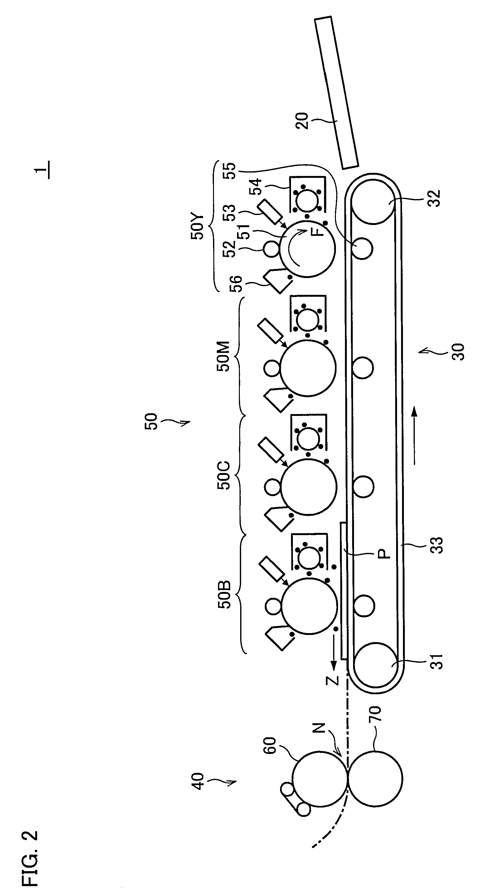
[0036]One embodiment of the present invention will be described below. Firstly explained is an image forming apparatus 1 in which a fixing apparatus of the present embodiment is provided, with reference to FIG. 2. FIG. 2 is a diagram schematically illustrating an internal structure of the image forming apparatus 1. The image forming apparatus 1 is a dry type electrophotographic color image forming apparatus, and is a printer for forming either a color image or a monochrome image on a sheet (recording material) P in accordance with either (i) image data transmitted from each of terminal devices connected to the image forming apparatus via a network, or (ii) image data read out by a scanner.

[0037]The image forming apparatus 1, the dry type electrophotographic color printer, is a 4-drum tandem type color printer and includes a visible image transferring section 50, a sheet transporting section 30, a fixing apparatus 40, and a sheet supply tray 20.

[0038]The visible image transferring se...


PUM


Abstract

For start of rotation of a fixing roller that is not currently being rotated, a control device causes a halogen lamp to heat an endless belt until a thermistor detects that a surface temperature of the endless belt has reached a first target temperature set at a temperature at which the endless belt is softened and is restored to its normal shape, from a deformed shape that the endless belt had while it was not rotated, to such an extent that the endless belt will never cause any rotation trouble during the rotation. This prevents the rotation trouble of the belt in a fixing apparatus in which a fixing member is heated by bringing the thus heated belt into contact with the fixing member.

Description

[0001]This Nonprovisional application claims priority under 35 U.S.C. §119(a) on Patent Application No. 2006 / 066668 filed in Japan on Mar. 10, 2006, the entire contents of which are hereby incorporated by reference.FIELD OF THE INVENTION[0002]The present invention relates to (i) a fixing apparatus provided in an electrophotographic image forming apparatus, (ii) a method for controlling the fixing apparatus, (iii) a control program, and (iv) a recording medium storing the control program.BACKGROUND OF THE INVENTION[0003]As a conventional fixing apparatus provided in an electrophotographic image forming apparatus, there is a roller pair type fixing apparatus made up of a fixing roller and a pressure roller.[0004]An example of such a fixing roller is a fixing roller in which a halogen lamp is provided as a heating source inside a hollow shaft that is made of a metal such as aluminum and that has a surface on which an elastic layer is provided. Generally, a temperature of a surface of t...

Claims


Application Information

Patent Timeline
Patent Type & Authority Patents(United States)
IPC IPC(8): G03G15/20
CPCG03G15/2039G03G2215/2016G03G2215/2019
Inventor MAEDA, TOMOHIROKAGAWA, TOSHIAKI
Owner SHARP KK
Why Eureka
Try Eureka