Single sided capacitive force sensor for electronic devices

a capacitive force sensor and electronic device technology, applied in the field of capacitive sensors, can solve the problems of increasing the cost of the overall electronic device, not providing an indication of the contact force being applied, and force sensitive resistors showing less desirable properties

Active Publication Date: 2010-08-31
GOOGLE TECH HLDG LLC
View PDF16 Cites 92 Cited by
  • Summary
  • Abstract
  • Description
  • Claims
  • Application Information

AI Technical Summary

Problems solved by technology

While capacitive touch sensors are useful for determining the geometric location of objects like fingers and styluses, they do not provide an indication of the contact force being applied.
However, when the user interface comprises only a fixed piece of glass or plastic, force sensitive resistors exhibit some less desirable properties.
Additionally, force sensitive resistors are costly, thereby increasing the cost of the overall electronic device.

Method used


Image

  • Single sided capacitive force sensor for electronic devices
  • Single sided capacitive force sensor for electronic devices
  • Single sided capacitive force sensor for electronic devices

Examples


Embodiment Construction

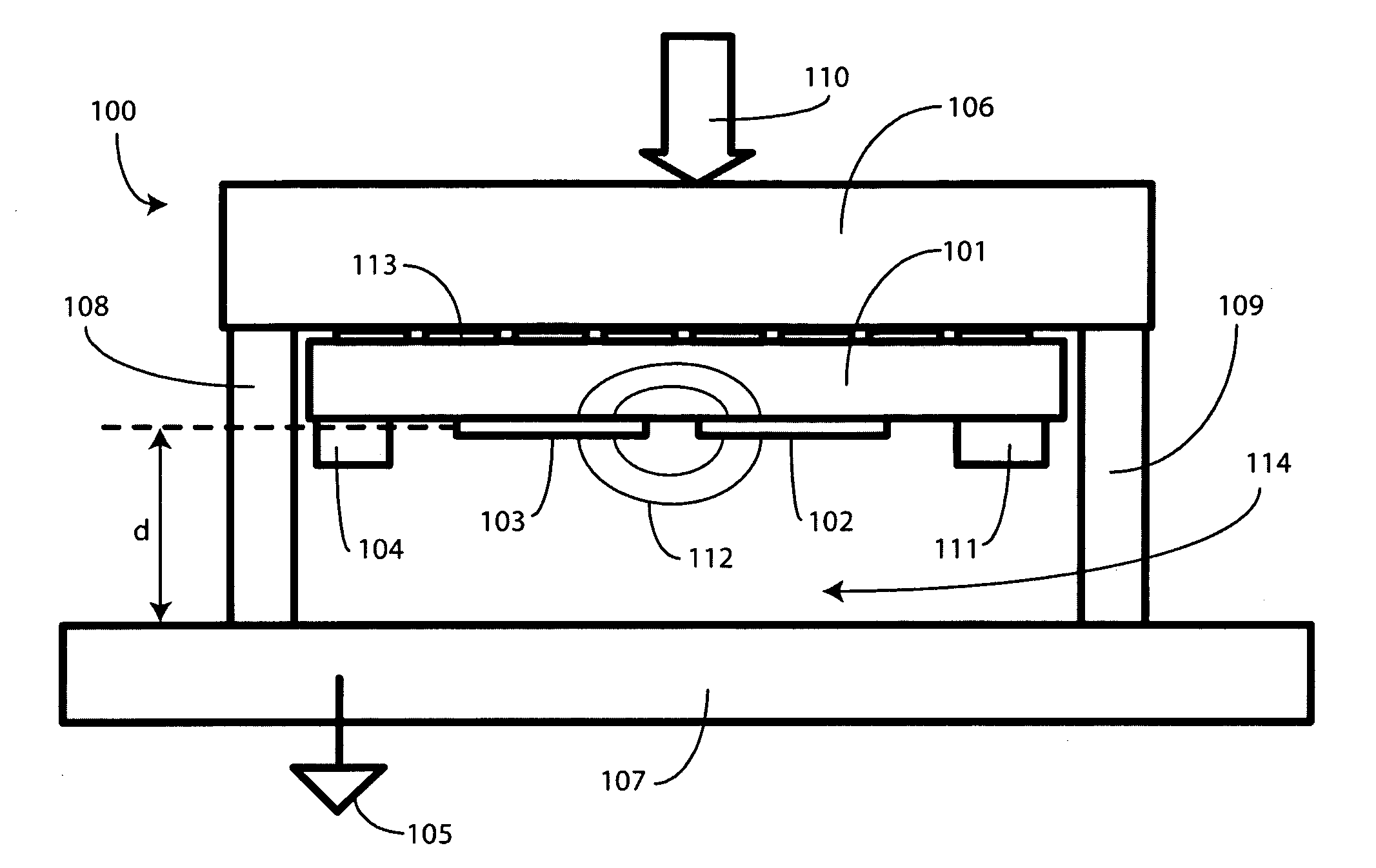
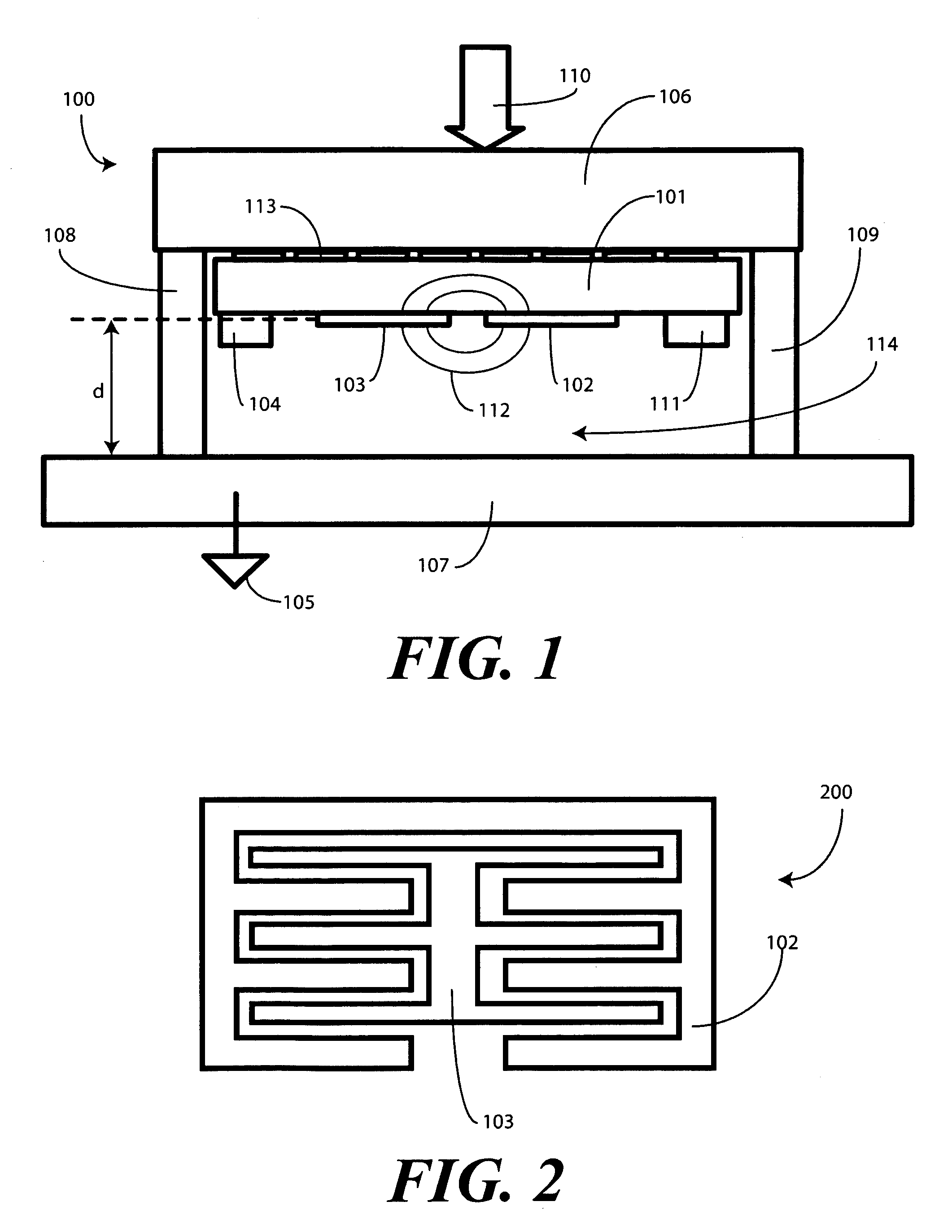
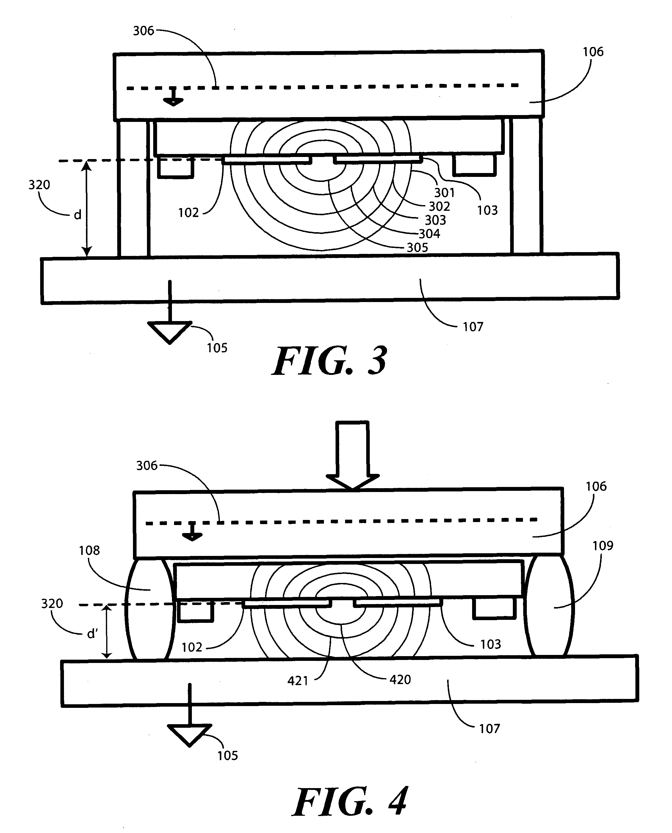
[0014]Before describing in detail embodiments that are in accordance with the present invention, it should be observed that the embodiments reside primarily in combinations of method steps and apparatus components related to capacitively detecting a contact force. Accordingly, the apparatus components and method steps have been represented where appropriate by conventional symbols in the drawings, showing only those specific details that are pertinent to understanding the embodiments of the present invention so as not to obscure the disclosure with details that will be readily apparent to those of ordinary skill in the art having the benefit of the description herein.

[0015]It will be appreciated that embodiments of the invention described herein may be comprised of one or more conventional processors and unique stored program instructions that control the one or more processors to implement, in conjunction with certain non-processor circuits, some, most, or all of the functions of e...


PUM

PropertyMeasurementUnit
capacitanceaaaaaaaaaa
voltageaaaaaaaaaa
compression forceaaaaaaaaaa

Abstract

A capacitive force sensor (100) includes a substrate (101) having at least one electrode pair (102,103) defining a capacitance disposed thereon. The substrate (101) is fixed relative to a first plate (106). A drive circuit (104) is configured to apply a voltage relative to a circuit ground (105) to the electrode pair (102,103). The first plate (106) is separated from a second plate (107) that is coupled to circuit ground (105) by a compliance member (108,109). The compliance member (108,109) is configured to oppose a compression force (110) while allowing the first plate (106) to physically move relative to the second plate (107). A capacitive detection circuit (111) is then configured to detect a change the capacitance when the compliance member (108,109) is compressed. The compression force (110) is then determined from the change in capacitance and the spring constant of the compliance member (108,109).

Description

BACKGROUND[0001]1. Technical Field[0002]This invention relates generally to capacitive sensors, and more particularly to a capacitive force sensor employing a capacitor pair disposed on a substrate to determine an amount of contact force.[0003]2. Background Art[0004]Portable electronic devices, including mobile telephones and personal digital assistants (PDAs), are becoming more sophisticated as the technology associated with these devices has continued to advance. For example, until recently, the user interface for a mobile telephone included twelve to fifteen mechanical buttons. Today, however, many portable devices include full QWERTY keypads. Further, some portable electronic devices employ touch sensitive screens that have no mechanical keys at all. Rather than pressing a mechanical button, the user simply touches a plastic or glass surface. Touch sensing circuits such as capacitive touch sensors then determine the location of the user's finger or stylus. A processor then corre...

Claims


Application Information

Patent Timeline
Patent Type & Authority Patents(United States)
IPC IPC(8): G01L1/12
CPCG01L1/142G06F3/044G06F3/0414G01L1/146G06F3/0443H03K17/955G06F2203/04103G06F2203/04107G06F2203/04112
Inventor DAVERMAN, DODGECRANFILL, DAVIDOLLEY, MICHAEL
Owner GOOGLE TECH HLDG LLC
Why Eureka
Try Eureka