
Reusable pellet shooting grenade

a grenade and pellet technology, applied in the field of replica grenades, can solve the problems of limiting the “effective range lagging reliability of the delay mechanism used in the previous pellet launching grenade to delay the “detonation” of the grenade after the grenade was activated, and the design of the previous pellet launching grenade was complicated to use and expensive to manufacture. , to achieve the effect o

Inactive Publication Date: 2010-08-31
CHONG CARLTON LE LOONG
View PDF45 Cites 16 Cited by
  • Summary
  • Abstract
  • Description
  • Claims
  • Application Information

AI Technical Summary

Benefits of technology

"The present invention provides an improved grenade with better reliability and performance. The grenade includes a launch tube with a breech end and a muzzle end, and multiple projectiles are loaded inside. A pressure source is connected to the breech end to launch the projectiles. The grenade also has a gas reservoir for storing compressed gas and a valve for controlling the flow of gas to propel the projectiles. A delay mechanism is included to slow down the movement of the valve. The grenade is triggered by a trigger mechanism and has a delay in the movement of the valve. Overall, this invention provides a more effective and reliable grenade for use in various situations."

Problems solved by technology

Firstly, the method of dispersing or launching the pellets did not impart much kinetic energy to the pellets; thereby greatly limiting the “effective range” of the grenade since the pellets would travel only a short distance.
The delay mechanisms used in previous pellet launching grenades to delay the “detonating” of the grenade after the grenade was activated also lacked reliability.
Furthermore, previous pellet launching grenade designs were complicated to use and expensive to manufacture.

Method used


Image

  • Reusable pellet shooting grenade
  • Reusable pellet shooting grenade
  • Reusable pellet shooting grenade

Examples


Embodiment Construction

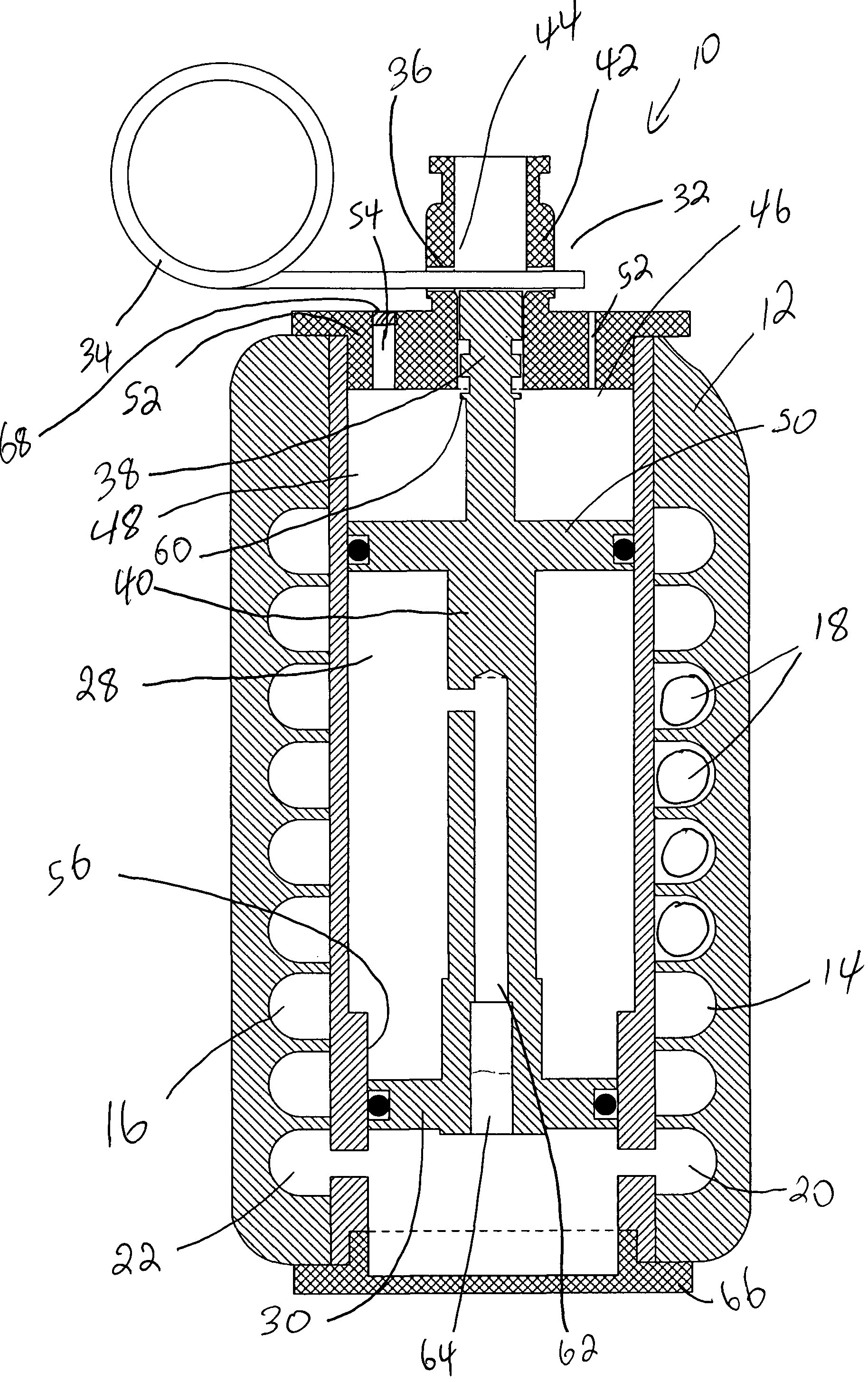
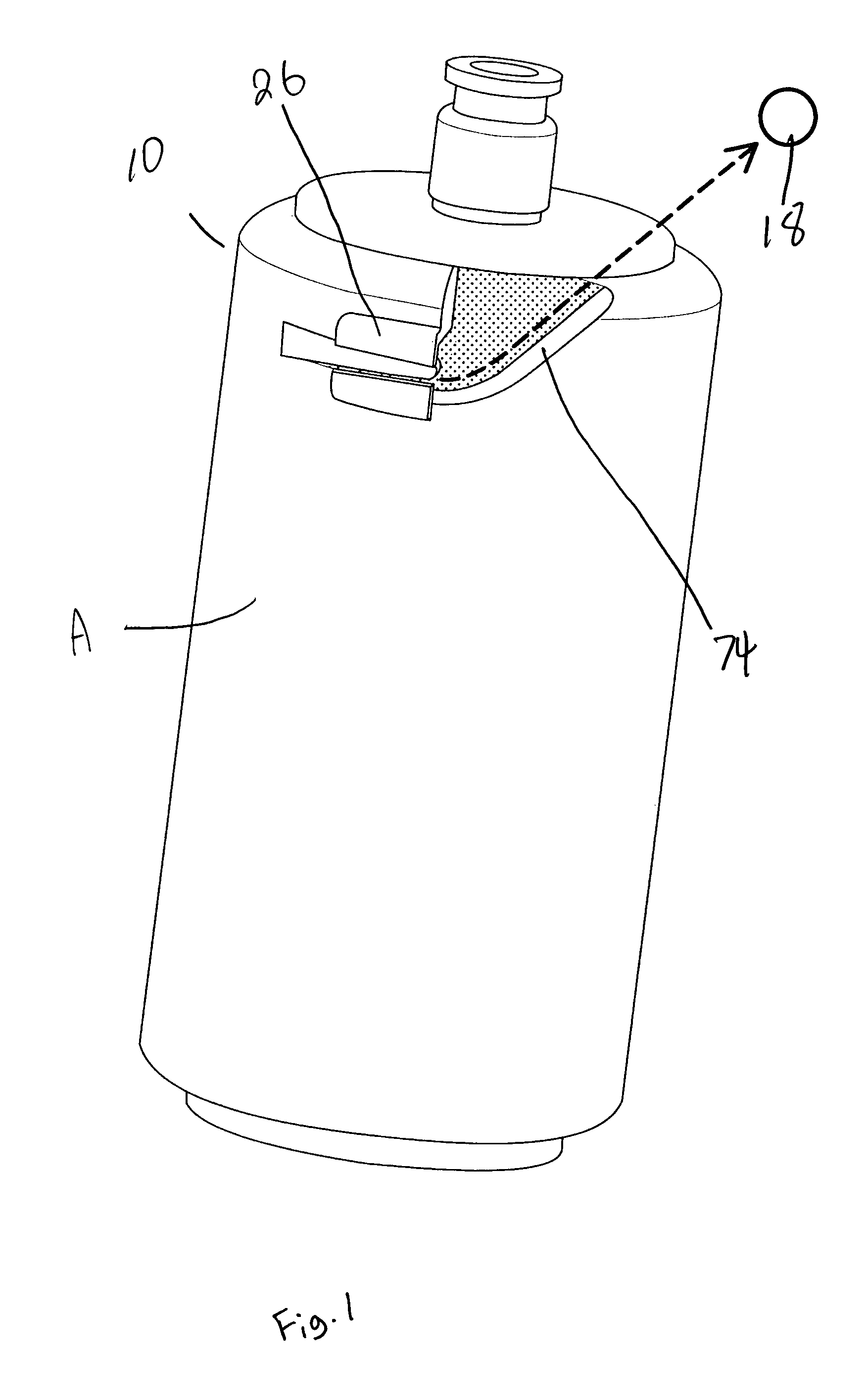
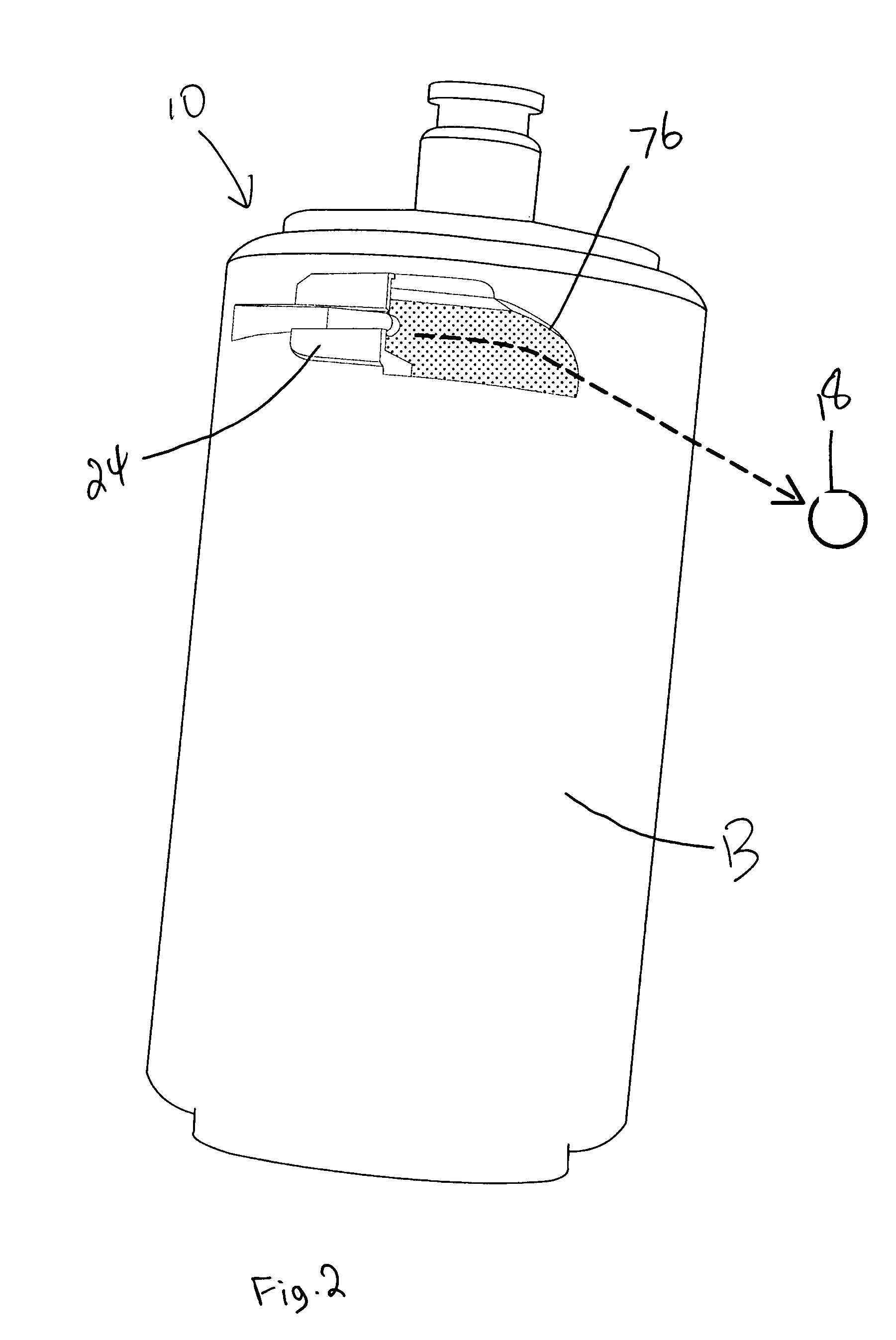
[0017]Referring firstly to FIGS. 7, 8 and 9, a grenade made in accordance with the present invention, shown generally as item 10 includes a housing 12 with a pair of spiral helical launch tubes 14 and 16 formed therein. Launch tubes 14 and 16 have breech ends 20 and 22 and muzzle ends 24 and 26 (see FIG. 5). A plurality of projectiles 18 are contained within the launch tubes. The grenade further includes a pressure source 28 for pressurizing the launch tubes sufficiently to launch the projectiles out of the launch tube. Pressure source 28 preferably consists of a gas reservoir for storing a quantity of compressed gas. Valve 30, is positioned between breech ends 22 and 20 and gas reservoir 28. Valve 30 is movable between a closed state, as shown in FIG. 7 where the valve prevents the flow of pressurized gas from reservoir 28 to breech ends 20 and 22, and an open state as shown in FIG. 9. As shall be explained later, valve 30 is biased towards its open position by the pneumatic pressu...


PUM


Abstract

The present invention is an improved grenade which launches a plurality of pellet projectiles. The grenade includes a housing containing at least one spiral launch tube, said launch tube having a breech end and a muzzle end. A plurality of projectiles are loaded in the launch tube between the breech and muzzle ends. The grenade includes a gas reservoir for storing a compressed gas coupled to the breech end of the launch tube. A valve is interposed between the reservoir and the breech end of the launch tube for controlling the flow of compressed gas from the reservoir to the breech end of the launch tube. The valve is moveable between a closed state and an open state wherein said compressed gas enters the breech end of the launch tube to propel the projectiles from the muzzle end, the valve being biased towards its open state. The grenade also includes a trigger mechanism coupled to the valve, the trigger mechanism operating between a locked state wherein the trigger mechanism holds the valve in its closed state and an unlocked state wherein the valve is free to move into its open state.

Description

FIELD OF THE INVENTION[0001]The invention relates generally to replica grenades for shooting plastic pellets.BACKGROUND OF THE INVENTION[0002]Pellet shooting grenades have been available for use in playing war simulation games. These grenades generally consisted of a hollow housing containing a quantity of pellets loosely contained in a chamber which was in close proximity to a pressurized air reservoir. A valve was generally provided between the air reservoir and the pellet containing chamber. Upon opening the valve, the flow of pressurized gas would cause the pellets to be propelled from the chamber. The pellet containing chamber was often made from several sections which would come apart when the valve was opened, thereby permitting the pellets a way of escaping the grenade when the grenade “detonated”. In many cases, a chemical propellant was used to create the gas pressure necessary for launching the pellets.[0003]While these prior pellet launching grenades do provide a means t...

Claims


Application Information

Patent Timeline
Patent Type & Authority Patents(United States)
IPC IPC(8): F41B11/00F41B11/62
CPCF41B11/62F42B8/26F42B12/58F42B27/00
Inventor CHONG, CARLTON LE LOONG
Owner CHONG CARLTON LE LOONG
Learn More