Valve monitoring and controlling system

a valve monitoring and control system technology, applied in the field of monitoring systems, can solve the problems of inability to easily detect the status or condition of the valve in the boat, the known system of remotely located valves in the boat is fraught with many shortcomings, and the valves are located within the hull of the boa

Inactive Publication Date: 2010-08-31
FORESMAN ROBERT
View PDF5 Cites 40 Cited by
  • Summary
  • Abstract
  • Description
  • Claims
  • Application Information

AI Technical Summary

Problems solved by technology

In this application, valves located within the hull of a boat are relatively inaccessible wherein the status thereof is not readily known at the bridge or helm location of the boat.
Unfortunately, the known system of remotely located valves in a boat is fraught with many shortcomings.
In the existing systems, it frequently happens that the status or condition of the valve is not readily discernible to the boat operator.
This situation can lead to many unpleasant and even disastrous results or events.
However, because hoses and / or clamps have limitations on the structural integrity thereof, suitable valves are used as required by marine regulatory agencies.
Consequently, these valves are accessible only with difficulty.
As a practical matter, most boat operators often do not check out the status of these valves.
Thus, an open valve can be a potential disaster in terms of flooding and, possible sinking, of the boat.
This can lead to the burn-up of the engine or generator because of lack of cooling.
This can lead to the undesirable rupture of an on-board hose.
Thus, there are described a few of the problems which can occur due to a valve being in a position (whether open or closed) which cannot be easily detected from the helm or other remote locations.

Method used


Image

  • Valve monitoring and controlling system
  • Valve monitoring and controlling system
  • Valve monitoring and controlling system

Examples


Embodiment Construction

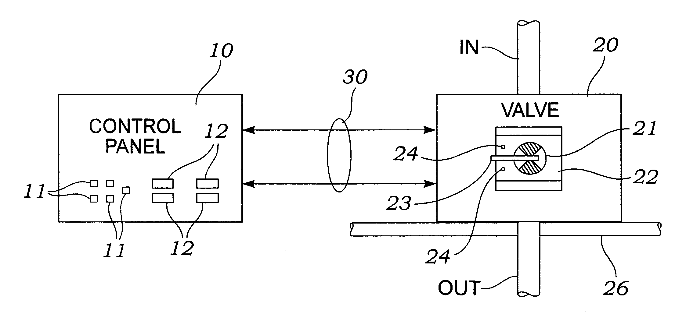
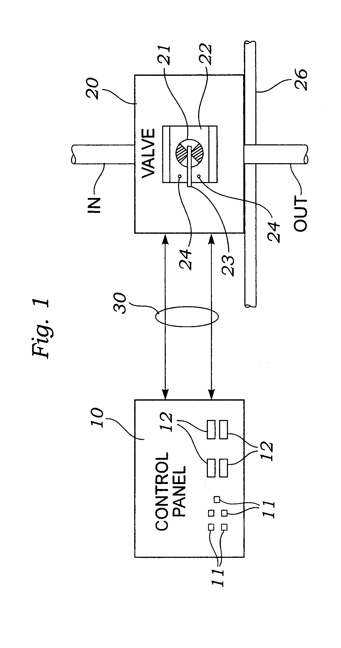
[0024]Referring now to FIG. 1, there is shown, in block diagram form, a schematic representation of the system of the instant invention. The control panel 10 is of any suitable construction. The control panel, in one application is mounted at a suitable and desirable location as, for example, the helm or bridge of boat. However, the invention is not limited specifically to such an application.

[0025]The valve 20 (shown diagrammatically) is of any suitable construction. The valve, in one application, takes the form of a ball valve or the like fabricated of Marelon. The valve includes a movable component 21 which selectively permits passage of material therethrough from the inlet (IN) to the outlet (OUT) ports (or vice versa). The movable component 21 is manipulated by a controller 23 which is, typically, a handle or the like.

[0026]An optional motor or drive mechanism (see infra) may be connected to the controller (handle) for selectively manipulating the valve condition in response to...


PUM


Abstract

A valve monitoring system including at least one valve having a movable handle with an activator therein mounted adjacent to a support panel on which are disposed a plurality of sensor devices responsive to the activator and a separate indicator panel for displaying the position of the valve handle. The activator at the handle and the sensor devices interact to selectively indicate operational conditions of the valve. In addition, a motor can be used to move the handle, and reconfigure the valve, as desired.

Description

BACKGROUND[0001]1. Field of the Invention[0002]The system of this invention is directed to a monitoring system, in general, and to a monitoring system which monitors and indicates the operational status of one or more valves which may be remotely located, in particular.[0003]2. Prior Art[0004]There are many known applications for remotely controlled valves. One specific application is found in the boating industry. In this application, valves located within the hull of a boat are relatively inaccessible wherein the status thereof is not readily known at the bridge or helm location of the boat.[0005]Unfortunately, the known system of remotely located valves in a boat is fraught with many shortcomings. In the existing systems, it frequently happens that the status or condition of the valve is not readily discernible to the boat operator. This situation can lead to many unpleasant and even disastrous results or events.[0006]For example, many boats include through hull fittings which ar...

Claims


Application Information

Patent Timeline
Patent Type & Authority Patents(United States)
IPC IPC(8): F16K37/00
CPCB63B13/02F16K37/0041Y10T137/8242Y10T137/8275Y10T137/8309
Inventor STEWART, RYALLFORESMAN, ROBERT
Owner FORESMAN ROBERT
Why Eureka
Try Eureka