Hybrid vehicle drive control system

a technology of drive control system and hybrid vehicle, which is applied in the direction of propulsion using engine-driven generators, electric propulsion mounting, transportation and packaging, etc., can solve the problems of loss of output torque, discomfort for the operator, and the drop of output torque to the drive wheels

Active Publication Date: 2010-08-31
NISSAN MOTOR CO LTD
View PDF41 Cites 55 Cited by
  • Summary
  • Abstract
  • Description
  • Claims
  • Application Information

AI Technical Summary

Benefits of technology

[0011]While disengaging the second clutch that is between the motor / generator and the transmission prevents the transmission of fluctuations to the drive wheels at engine startup caused by engagement of the first clutch, unfortunately, the output torque to the drive wheels during engine cranking will fall to 0 and create a sense of loss of output torque. The present invention is based on recognition of the fact that it is possible to solve the abovementioned problems by slip engaging the second clutch instead of fully engaging as in the conventional case. Accordingly, one object of the present invention is to provide a hybrid vehicle drive control system that embodies this concept and solves the abovementioned problems.

Problems solved by technology

Consequently, there is a risk that the output torque to the drive wheels will fall to 0 and the absence of the output torque during cranking of the engine will be felt, and cause discomfort for the operator, particularly during vehicle acceleration.
While disengaging the second clutch that is between the motor / generator and the transmission prevents the transmission of fluctuations to the drive wheels at engine startup caused by engagement of the first clutch, unfortunately, the output torque to the drive wheels during engine cranking will fall to 0 and create a sense of loss of output torque.

Method used


Image

  • Hybrid vehicle drive control system
  • Hybrid vehicle drive control system
  • Hybrid vehicle drive control system

Examples


Embodiment Construction

[0033]Selected embodiment of the present invention will now be explained with reference to the drawings. It will be apparent to those skilled in the art from this disclosure that the following description of the embodiment of the present invention is provided for illustration only and not for the purpose of limiting the invention as defined by the appended claims and their equivalents.

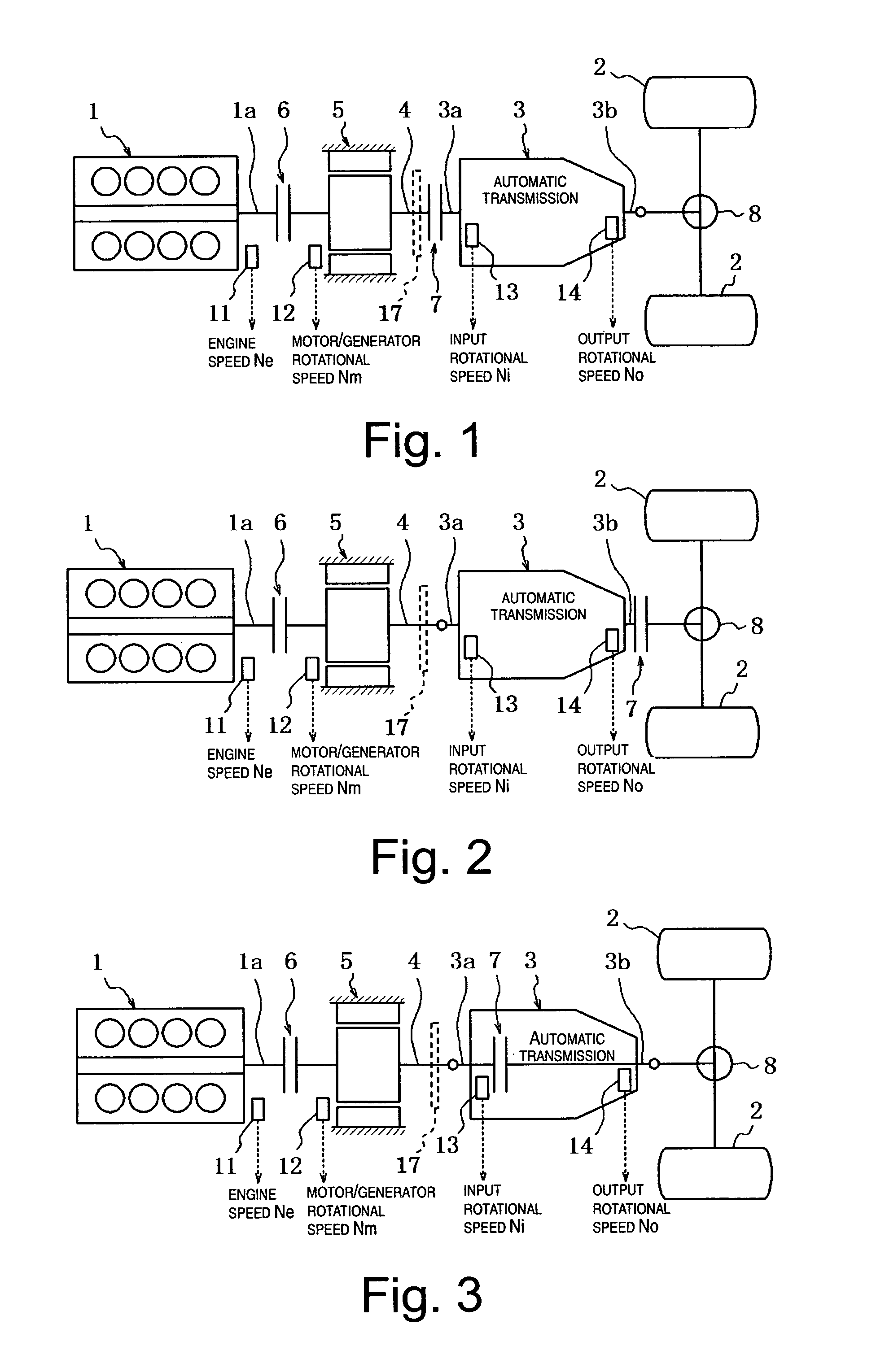
[0034]Referring initially to FIGS. 1 to 3, a front engine / rear wheel drive vehicle (rear wheel drive hybrid vehicle) is illustrated in each of the Figures in which each of the hybrid vehicles is equipped with a hybrid vehicle drive control system in accordance with one preferred embodiment of the present invention. Basically, the hybrid vehicles of FIGS. 1 to 3 illustrate three examples of alternate power trains of hybrid vehicles in which the hybrid vehicle drive control system in accordance with the present invention can be applied. In these examples, each hybrid vehicle includes, among other things,...


PUM


Abstract

A hybrid vehicle drive control system is configured to perform engine startup when switching from an electric drive mode to a hybrid drive mode, without creating a sense of output torque loss. In particular, a controller selectively controls a first clutch disposed between the engine and the motor / generator and a second clutch disposed between the motor / generator and a drive wheel to switch between an electric drive mode in which the first clutch is released and the second clutch is engaged, and a hybrid drive mode in which both the first and second clutches are engaged. The controller sets the second torque transfer capacity to a value that is more than zero and less than the target motor / generator torque of the motor / generator when switching from the electric drive mode to the hybrid drive mode and when starting the engine.

Description

CROSS-REFERENCE TO RELATED APPLICATIONS[0001]This application claims priority to Japanese Patent Application No. 2005-322406, filed on Nov. 7, 2005. The entire disclosure of Japanese Patent Application No. 2005-322406 is hereby incorporated herein by reference.BACKGROUND OF THE INVENTION[0002]1. Field of the Invention[0003]The present invention generally relates to a hybrid vehicle drive control system for a hybrid vehicle having an electric drive (EV) mode in which a drive wheel is solely driven by a motor / generator and a hybrid drive (HEV) mode in which the drive wheel is driven by an engine and the motor / generator, or the engine only. More particularly, the present invention relates to a hybrid vehicle drive control system that is configured to control a torque transfer capacity of a clutch to start the engine from the torque of the when motor / generator switching to the latter the hybrid drive (HEV) mode from the electric drive (EV) mode.[0004]2. Background Information[0005]Vario...

Claims


Application Information

Patent Timeline
Patent Type & Authority Patents(United States)
IPC IPC(8): B60W10/02B60K6/48B60K6/54B60L50/16B60W10/08B60W20/00F16D48/02
CPCB60K6/48B60W10/02B60W10/06B60W10/08B60W20/00B60L2240/423B60L2240/486B60L2200/26B60W2710/027B60W2710/083B60W2710/105Y02T10/6221Y02T10/6286Y02T10/642B60L15/2036B60L15/2054B60L2240/421B60L2240/441B60L2240/507Y02T10/72B60L50/16Y02T10/62Y02T10/64Y02T10/7072B60K2006/268B60K6/38B60W20/40B60W20/10Y02T10/70
Inventor YAMANAKA, TSUYOSHIKOUNO, KAZUYUKIUENO, MUNETOSHIOKUDA, TADASHIJOE, SHINICHIROONOYAMA, TAIICHIHIDAKA, TERUMASATSUCHIKAWA, HARUHISAITO, KENADACHI, KAZUTAKA
Owner NISSAN MOTOR CO LTD
Why Eureka
Try Eureka