Al technical title is built by PatSnap Al team. It summarizes the technical point description of the patent document.
a radiotherapy and radiotherapy technology, applied in the direction of patient positioning for diagnostics, therapy, application, etc., can solve the problems of increasing the cost per treatment, affecting the treatment effect, and the radiation beam being misaligned with the target tissu
Inactive Publication Date: 2010-09-07
LOMA LINDA UNIV MEDICAL CENT
View PDF325 Cites 48 Cited by
Summary
Abstract
Description
Claims
Application Information
AI Technical Summary
This helps you quickly interpret patents by identifying the three key elements:
Problems solved by technology
Method used
Benefits of technology
[0018]According to one embodiment of the present invention, there is provided a device for aligning a patient for delivering a plurality of radiation beams. The device comprises a patient support surface, a coarse alignment subsystem connected to the patient support surface, and a fine alignment subsystem connected to the patient support surface. In one embodiment, the patient support surface comprises a table. In another embodiment, the coarse alignment subsystem can induce coarse movements of the patient support surface comprising translation motions of as large as about 2 m, and rotations of as large as about 60°. In another embodiment, the coarse alignment subsystem comprises an elevating column. In another embodiment, the coarse alignment subsystem further comprises a base and a plurality of wheels connected to the base. In another embodiment, the coarse alignment subsystem further comprises a base and a counterweight connected to the base. In another embodiment, the device further comprises electronics to control movement of the coarse alignment subsystem. In another embodiment, the coarse alignment subsystem comprises a position detection system to calculate the position of the device. In another embodiment, the device further comprises an interface for affixing one or more than one registration and immobilization device connected to the patient support surface. In a preferred embodiment, the fine alignment subsystem can induce fine movements of the patient support surface comprising translation motions as large as about ±20 mm with a resolution of between about 0.04 mm and 0.1 mm resolution in three perpendicular axes, and pitch and roll rotations as large as about ±5° with a resolution of between about 0.1° and 0.2°. In another preferred embodiment, the fine alignment subsystem can induce fine movements of the patient support surface comprising translation motions as large as about ±20 mm with about 0.05 mm resolution in three perpendicular axes, and pitch and roll rotations of as large as about ±5° with a resolution of about 0.1°. In another embodiment, the device further comprises electronics to control movement of the fine alignment subsystem.
Problems solved by technology
Second, protons lose energy at a more rapid rate as they penetrate tissue, thereby delivering a greater dose at the depth of the target tissue.
Unfortunately, radiation beam delivery devices within the gantry are prone to flex when rotated and, thereby, cause misalignment of the radiation beam with the target tissue.
Disadvantageously, however, radiographically repositioning a patient requires at least about 15 minutes to align each radiation beam prior to radiation delivery.
Hence, radiographically repositioning a patient for each radiation beam significantly limits the number of patients that can be treated by each treatment apparatus and increases the cost per treatment.
Method used
Image
Click on the blue label to locate the original text in one second.
Reading with bidirectional positioning of images and text.
Examples
Embodiment Construction
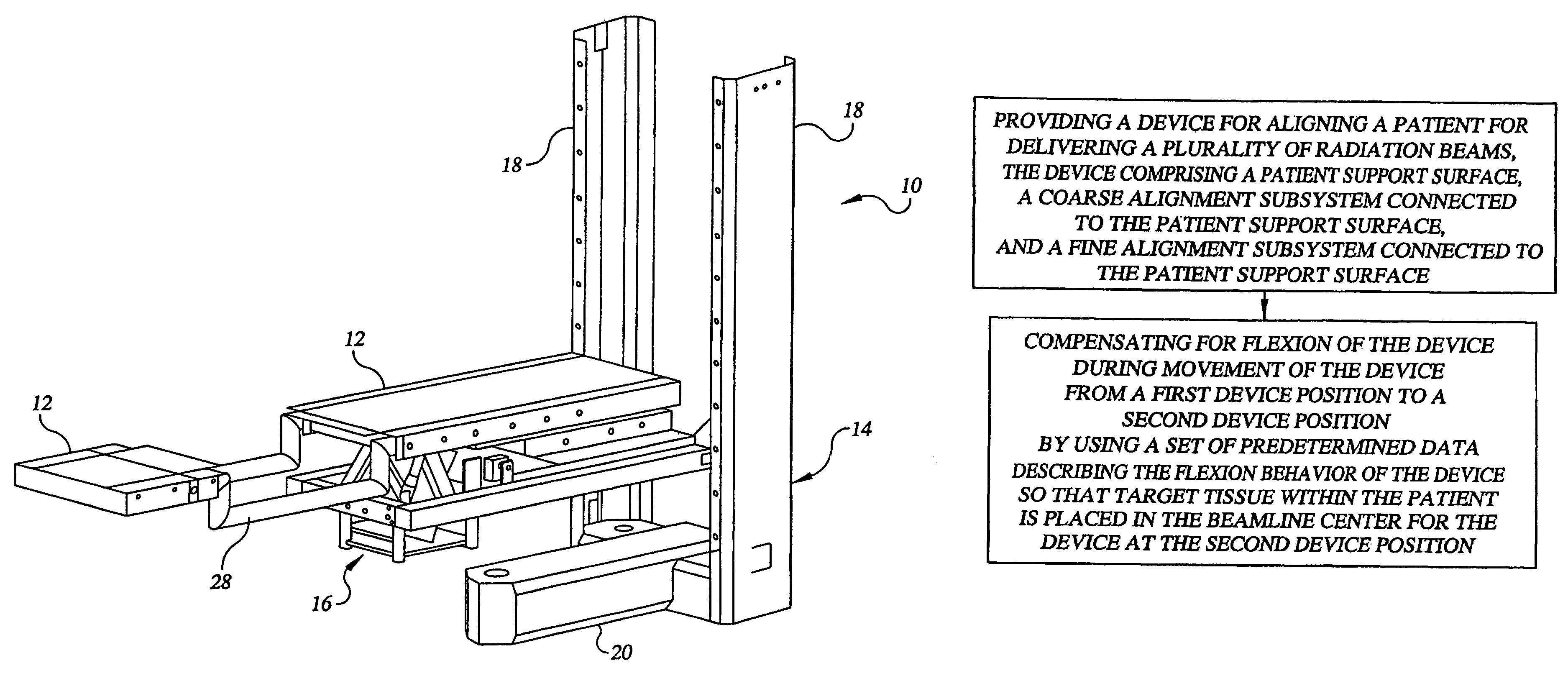
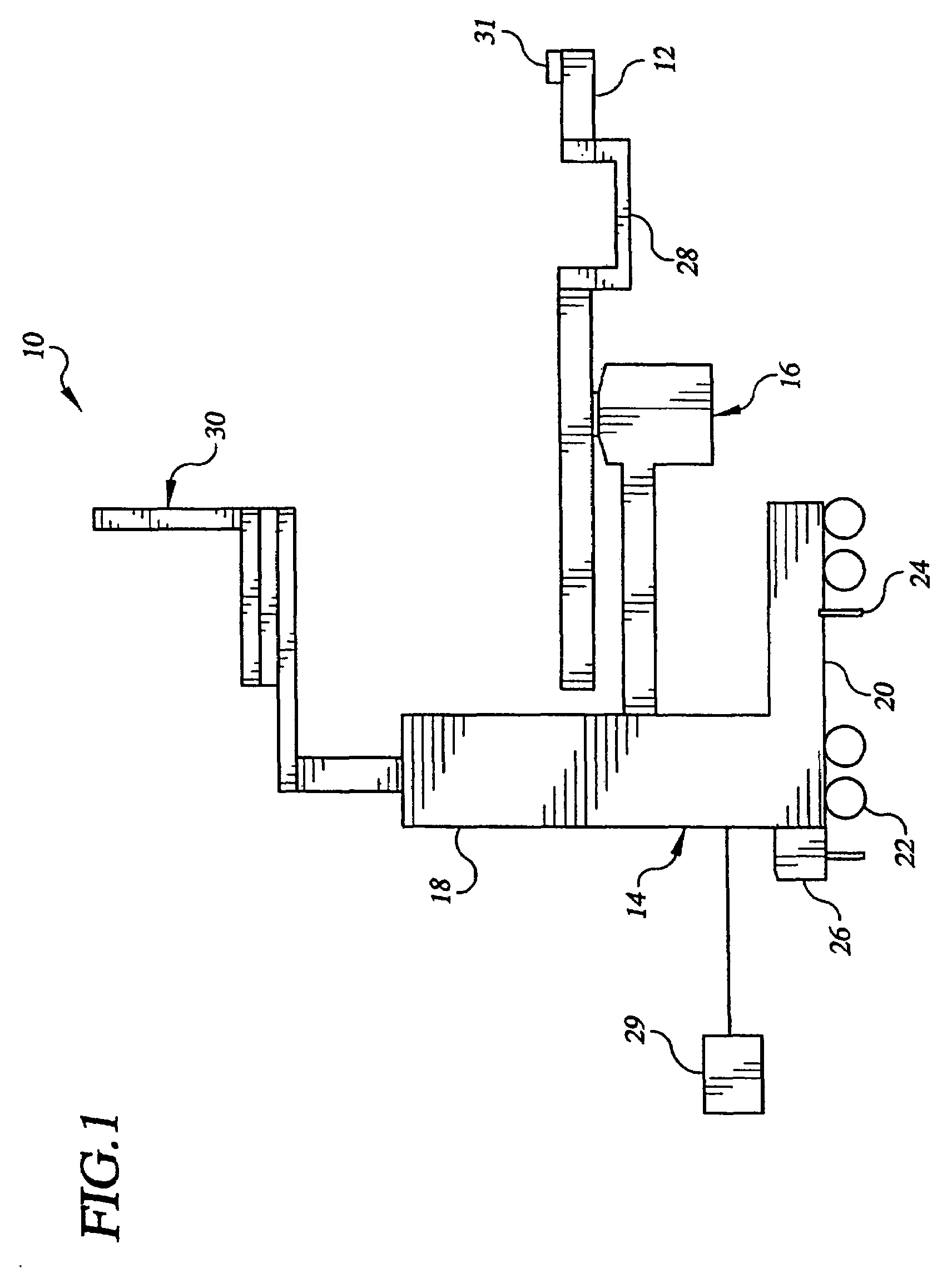
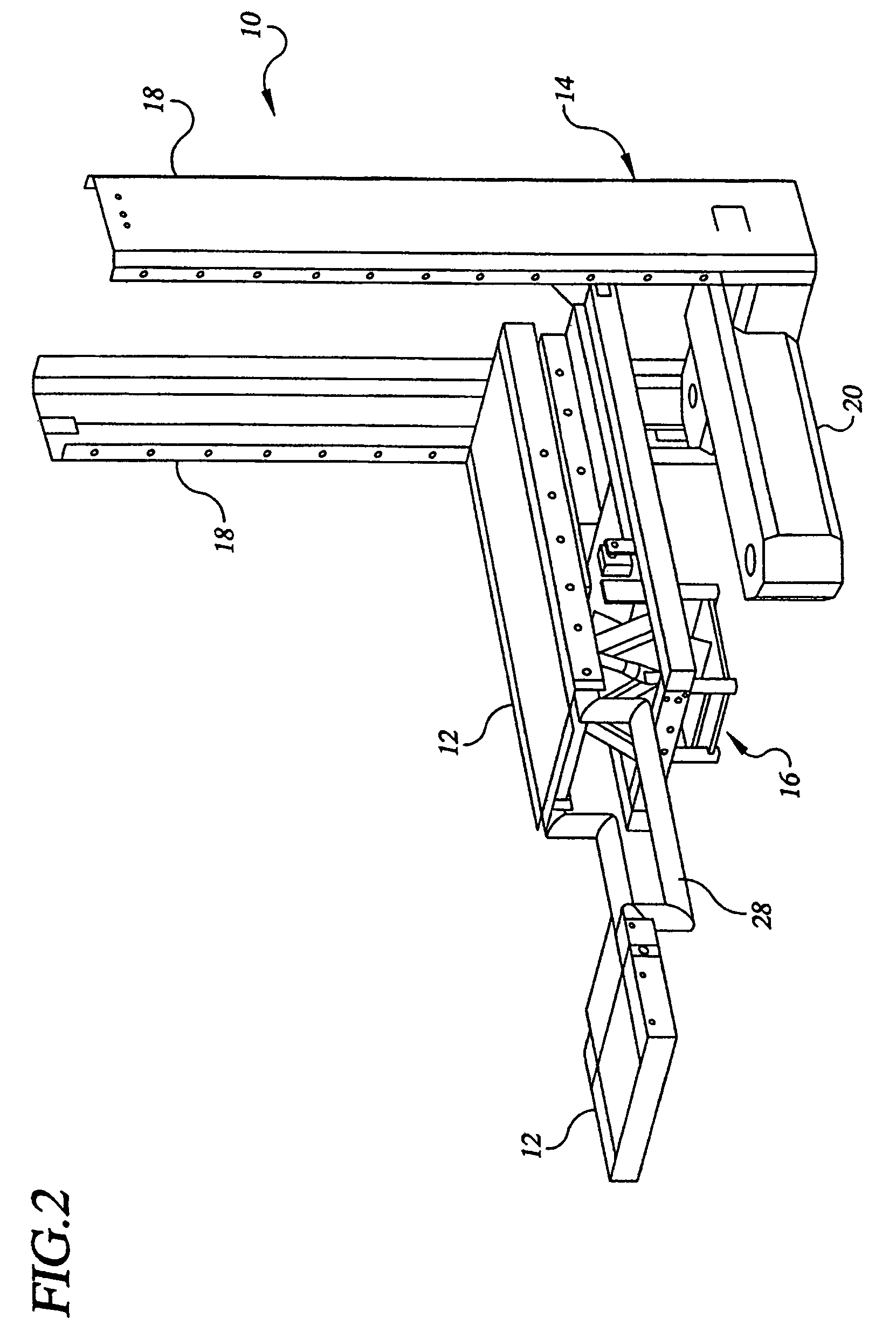
[0038]According to one embodiment of the present invention, there is provided a device for aligning a patient for delivering a plurality of radiation beams, such as proton beams, from a radiation beam delivery device at a plurality of device positions that allows a patient to be aligned in less time than using conventional aligning devices. According to another embodiment of the present invention, there is provided a method of aligning a patient for delivering a plurality of radiation beams, such as proton beams, from a radiation beam delivery device at a plurality of device positions. The method allows a patient to be aligned in less time than using conventional methods. By reducing the amount of time for alignment, both the device and the method allow an increased number of patients to be treated, decrease the cost of treatment per patient, and reduce the amount of radiation exposure to non-target tissues resulting from the alignment process. According to another embodiment of the...
PUM
Abstract
A device 10 for aligning a patient for delivering a plurality of radiation beams comprising a patient support surface 12, a coarse alignment subsystem 14 connected to the patient support surface, and a fine alignment subsystem connected to the patient support surface 16. A method of aligning a patient for delivering a plurality of radiation beams from a plurality of device positions comprising compensating for flexion of a radiation beam delivery device within a gantry during movement of the radiation beam delivery device from a first device position to a second device position by using a set of predetermined data describing the flexion behavior of the radiation beam delivery device so that the target tissue within the patient is placed at the beamline center for the radiation beam delivery device at the second device position.
Description
CROSS-REFERENCE TO RELATED APPLICATIONS[0001]The present application is a continuation of U.S. patent application Ser. No. 11 / 314,138, filed Dec. 21, 2005 which is a continuation of U.S. patent application Ser. No. 10 / 887,507, filed Jul. 7, 2004, now U.S. Pat. No. 7,011,447, which is a continuation of U.S. application Ser. No. 10 / 393,836, filed Mar. 20, 2003, now U.S. Pat. No. 6,769,806, which claims priority from International Patent Application PCT / US02 / 34556, entitled “Method and Device for Delivering Radiotherapy,” filed Oct. 28, 2002, which claims the benefit of U.S. Provisional Patent Application 60 / 340,430, filed Oct. 30, 2001, entitled “Method and Device for Delivering Radiotherapy,” the contents of which are incorporated herein by reference in their entirety.STATEMENT REGARDING FEDERALLY SPONSORED RESEARCH OR DEVELOPMENT[0002]This invention was made with United States Government support under Cooperative Agreement Number DAMD17-97-2-7016 with the National Medical Technology...
Claims
Application Information
Patent Timeline
Application Date:The date an application was filed.
Publication Date:The date a patent or application was officially published.
First Publication Date:The earliest publication date of a patent with the same application number.
Issue Date:Publication date of the patent grant document.
PCT Entry Date:The Entry date of PCT National Phase.
Estimated Expiry Date:The statutory expiry date of a patent right according to the Patent Law, and it is the longest term of protection that the patent right can achieve without the termination of the patent right due to other reasons(Term extension factor has been taken into account ).
Invalid Date:Actual expiry date is based on effective date or publication date of legal transaction data of invalid patent.