
Integrated external beam radiotherapy and MRI system

a magnetic resonance imaging and beam radiotherapy technology, applied in radiation therapy, x-ray/gamma-ray/particle irradiation therapy, medical science, etc., can solve the problems of electron beam deflection, method has a fundamental difficulty, and the apparatus interferes with the operation of the linear accelerator

Active Publication Date: 2009-06-11
ALBERTA HEALTH SERVICES
View PDF37 Cites 100 Cited by
  • Summary
  • Abstract
  • Description
  • Claims
  • Application Information

AI Technical Summary

Benefits of technology

[0018]an interface between the radiation source and the MRI apparatus that permits irradiation to be performed simultaneously with imaging, wherein the MRI apparatus and radiation source are coupled such that the system can be used in a rotation mode whereby the radiation source can irradiate a subject from basically any angle without reducing MRI image quality.
[0020]In one embodiment, the radiation source can be rotated without affecting the homogeneity of the MRI magnetic field. Alternatively, in another embodiment, the radiation source and MRI apparatus are held stationary with rotation therapy being achieved through rotation of the subject.
[0021]In one embodiment, pulsing of the radiation source does not occur at the same time as RF signal read-back of the MRI apparatus. Also, RF noise that can interfere with the RF signal read-back of the MRI apparatus is reduced.
[0029]In another embodiment, the system further comprises a two-dimensional imaging device. The imaging device captures one of megavoltage axial and computed tomography images simultaneously with MR images for beam verification, registration and generation of attenuation data used in treatment planning calculations. Alternatively or in conjunction with, the imaging device captures SPECT images simultaneously with MR images for improved diagnostic information and treatment planning.
[0034]In one embodiment, radiation source driving pulses are interrupted during MRI apparatus RF signal reading. Also, RF noise generated by the radiation source that can interfere with MRI apparatus RF signal reading is reduced by shaping the radiation source driving pulses.
[0035]The integrated radiation source and MRI system allows the radiation source and MRI apparatus to operate effectively without the radiation source and MRI apparatus interfering with one another during operation. This allows images of the subject to be captured and used to ensure that the beam of radiation generated by the radiation source is directed properly to the target tissue during radiotherapy treatment fractions.

Problems solved by technology

Unfortunately, this method has a fundamental difficulty if the image used to define the target volume is acquired in a single simulation since it is not known if image guided reproduction of the target location in subsequent treatment fractions results in the planned dosimetry being accurately delivered to the target and non-target tissues.
Integrating a linear accelerator with an MRI apparatus poses several technical problems.
For example, the magnetic field generated by the MRI apparatus interferes with the operation of the linear accelerator.
In particular, the magnetic field generated within the MRI apparatus interferes with the trajectory of the electron beam in the linear accelerator through the magnetic force F=qvB and can cause the electron beam to deflect.
Even for a partially deflected electron beam, the altered angle of incidence on the heavy metal target may cause sufficient perturbation to the bremstrahlung x-ray beam to cause it to be unacceptable clinically.
In addition, the presence of the linear accelerator perturbs the magnetic field generated by the MRI apparatus.
This in itself is not a problem since this can be compensated for; however, if this material is moved (for instance if this material were a linear accelerator, or the shielding surrounding a cobalt source), the dynamic perturbation of the magnetic field in the homogeneous region could cause unacceptable image distortions.
This problem would exist for both linear accelerator and cobalt based radiotherapy.
Still further problems exist in that the RF fields generated by the linear accelerator interfere with the receiver coils of the MRI apparatus.
The significant shielding required for the cobalt source may corrupt MR image quality during rotation.

Method used


Image

  • Integrated external beam radiotherapy and MRI system
  • Integrated external beam radiotherapy and MRI system
  • Integrated external beam radiotherapy and MRI system

Examples


Embodiment Construction

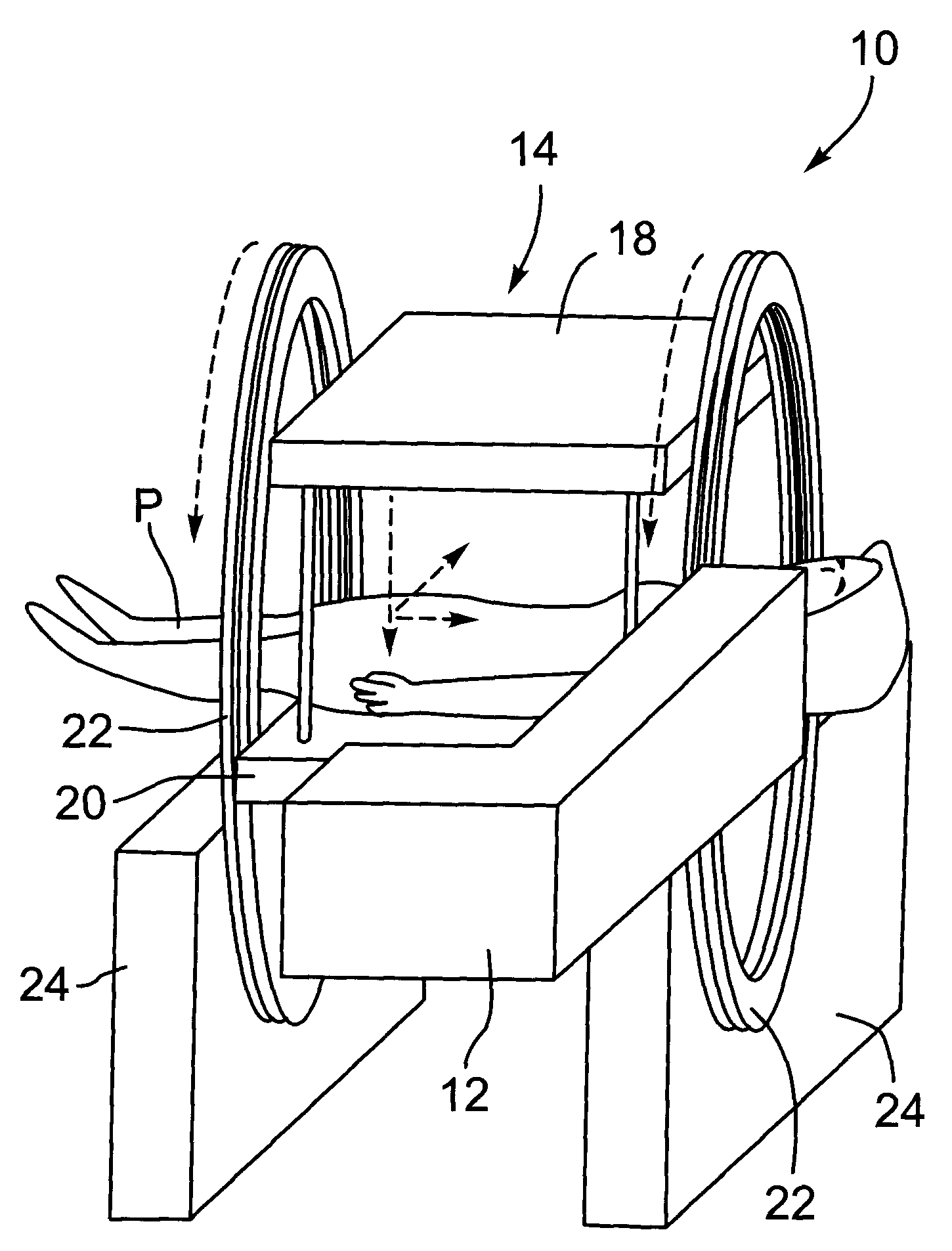
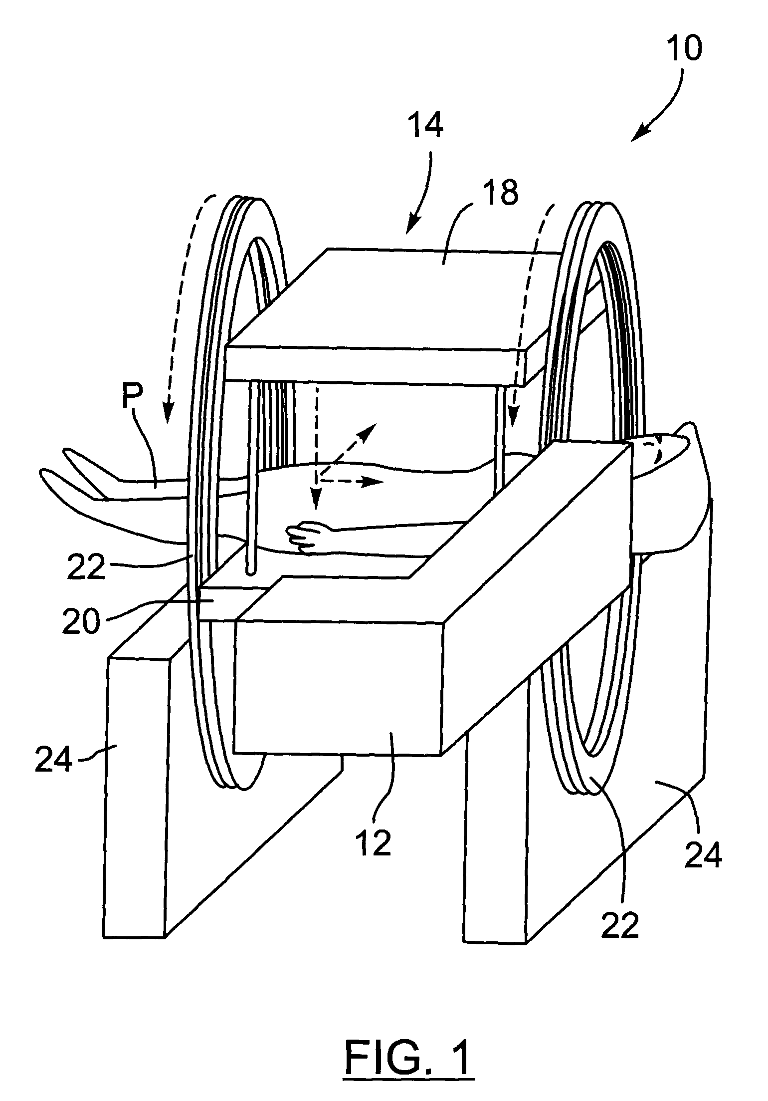
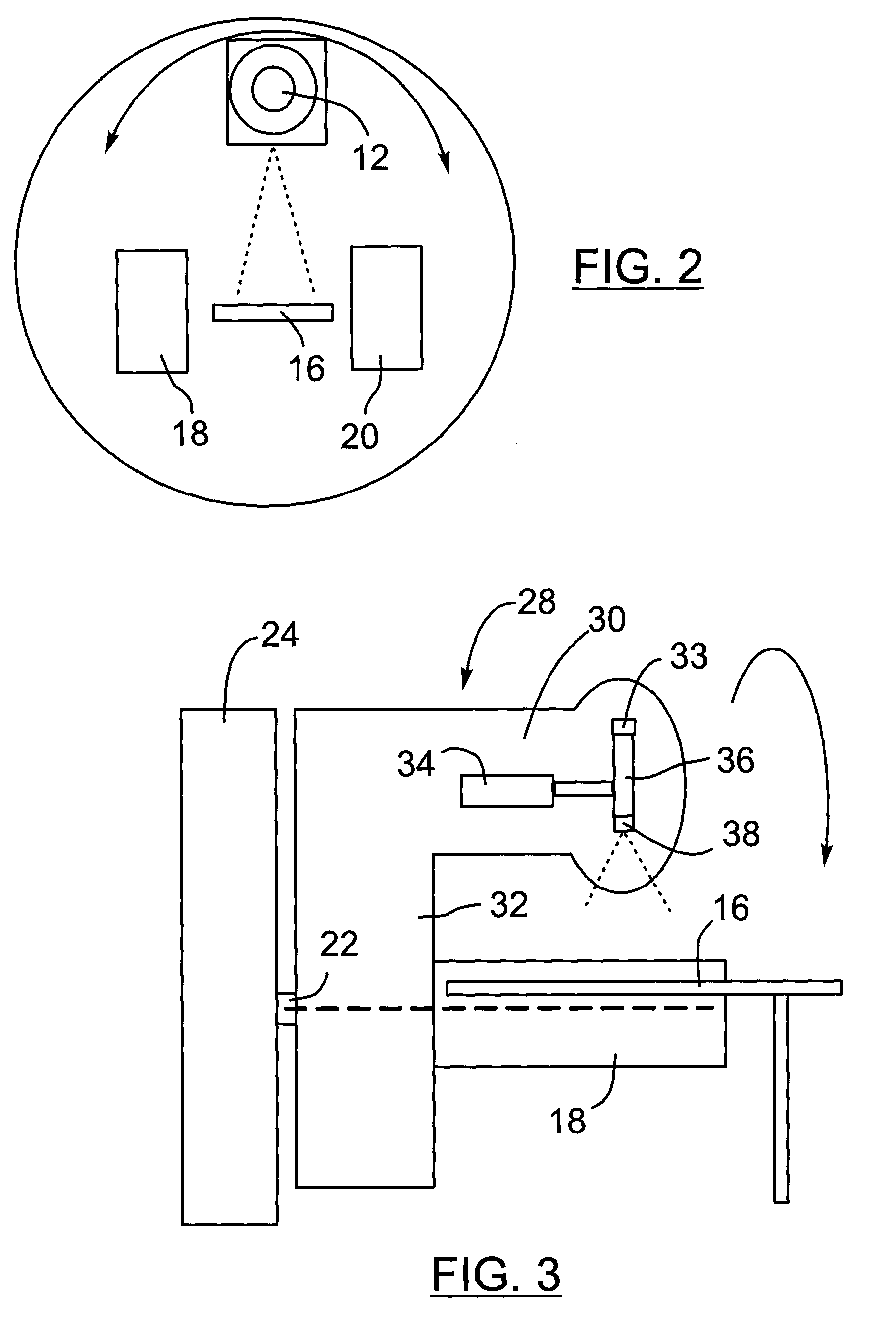
[0044]Turning now to FIGS. 1 to 3, an integrated linear accelerator and MRI system is shown and is generally identified by reference numeral 10. As can be seen, the integrated linear accelerator and MRI system 10 includes a linear accelerator (“linac”) 12 and an MRI apparatus 14. Linac within the context of the present application refers to virtually any radiation source, such as for example a particle accelerator or radioisotope source, capable of generating a beam of radiation including for example x-rays, gamma rays, electrons, protons, helium ions, carbon ions, other heavy ions or neutrons.

[0045]In this particular example, the MRI apparatus 14 has a 0.2 T magnetic field strength and is of the open bore type including a table 16 on which a patient P can lay and be moved into and out of the opening for the magnet / linac. The poles 18 and 20 of a polarizing magnet are disposed above and below the table 16. The magnet poles 18 and 20 are mounted on a rotating gantry 22 that is suppor...


PUM


Abstract

A radiation therapy system comprises a radiation source generating a beam of radiation and a magnetic resonance imaging apparatus. An interface acts between the radiation source and the MRI apparatus that permits irradiation to be performed simultaneously with imaging. The MRI apparatus and radiation source are coupled such that the system can be used in a rotation mode whereby the radiation source can irradiate a subject from basically any angle without reducing MRI image quality.

Description

FIELD OF THE INVENTION[0001]The present invention relates generally to radiation therapy and in particular to an integrated external beam radiotherapy and magnetic resonance imaging (MRI) system.BACKGROUND OF THE INVENTION[0002]Radiation therapy can be given to treat proliferative tissue disorders including but not limited to cancer, arteriovenous malformations, dermatological lesions etc. During radiation therapy, the tissue of the patient known to or suspected to contain the disease is exposed to radiation. Linear accelerators are commonly used to irradiate a target volume encompassing the tissue to be treated during radiation therapy. As is known, linear accelerators use microwave technology to accelerate electrons in a waveguide and then allow the electrons to collide with a heavy metal target. As a result of the collisions, high-energy x-rays are scattered from the target. A portion of the scattered x-rays is collected and shaped by a beam collimating device to form an output b...

Claims


Application Information

Patent Timeline
IPC IPC(8): A61B5/055A61N5/10A61N5/00
CPCA61B5/055A61N2005/1055A61N5/1081A61N5/1049A61B6/405A61B6/4064
Inventor FALLONE, B. GINOCARLONE, MARCOMURRAY, BRAD
Owner ALBERTA HEALTH SERVICES
Learn More