Multi-channel integrated MRI transmitter system for a magnetic resonance imaging device

a magnetic resonance imaging and integrated technology, applied in the field of rf transmitter coil systems, can solve the problems of not making frequency and amplitude adjustments, and the phase between two channels cannot be changed

Active Publication Date: 2021-09-28
ASELSAN ELEKTRONIK SANAYI & TICARET ANONIM SIRKETI
View PDF2 Cites 0 Cited by
  • Summary
  • Abstract
  • Description
  • Claims
  • Application Information

AI Technical Summary

Benefits of technology

[0007]The most important difference of the invention from present embodiments is the minimization of the interference effects occurring because of the RF coupling between multiple RF cables, one for each channel, that carries the high RF power from the amplifiers into the Faraday cage. Beside this, elimination of the RF cabling from outside into the Faraday cage any RF noise leakage to the Faraday cage will be reduced. Several channels can be controlled by means of one single fiber optic line thanks to carrying signal generator modulators into the chamber, where the MRI system is located. Full digitalization of the system contributes a high programmable flexibility to the system. One single RF pulse can be modulated by carrier signal of more than one different frequency by use of delta sigma modulation, which provides speeding up through multiple slice selection by one single pulse during MRI scan. It also provides cost effectiveness by use of digital RF power amplifiers of lower power and located in distributed architecture instead of high cost and high output power single analogue RF power amplifier in conventional systems, and it is also capable to work at adequate performance in case of power amplifier failure.DETAILED DESCRIPTION OF THE INVENTION

Problems solved by technology

In this system, the phase between two channels can not be changed and can not make frequency and amplitude adjustment independent of each other.

Method used


Image

  • Multi-channel integrated MRI transmitter system for a magnetic resonance imaging device
  • Multi-channel integrated MRI transmitter system for a magnetic resonance imaging device

Examples


Embodiment Construction

[0008]In order to achieve the purpose of the invention, multi-channel RF transmitter coil chain system for a magnetic resonance imaging device is shown in the attached figures, which are:

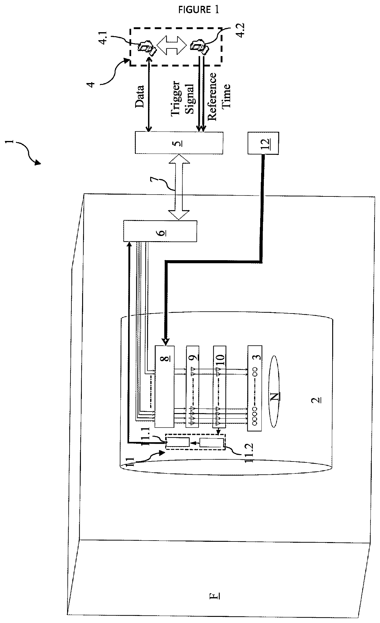
[0009]FIG. 1 is a schematic view of RF transmitter system for magnetic resonance imaging device.

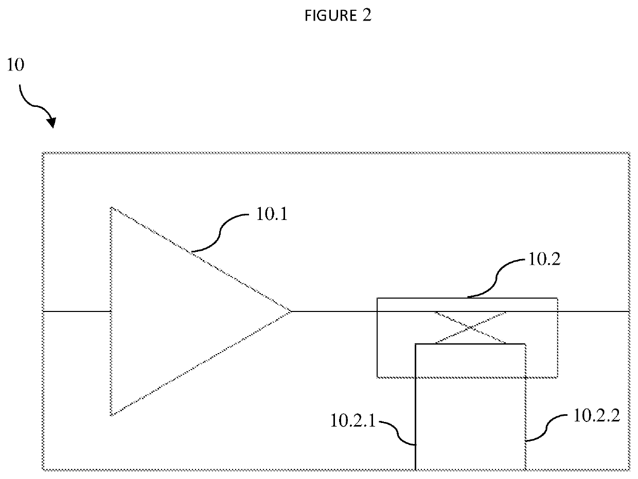
[0010]FIG. 2 is a schematic view of internal structure of RF power amplifier module.

[0011]The parts indicated in the figures have been designated separate numbers and said numbers are given below:[0012]1. Multi-channel RF transmitter system[0013]2. Magnetic resonance imaging device[0014]3. Coil array[0015]4. Control device[0016]4.1. Interface control computer[0017]4.2. MRI control computer[0018]5. Interface control module[0019]6. Signal modulator and control module[0020]7. Fibre optic line[0021]8. Power / data distribution module[0022]9. RF driver module[0023]10. Power amplifier module[0024]10.1. Power amplifier block[0025]10.2. Coupler[0026]10.2.1. Transmitted Power measurement channel[0027]10.2.2. Returni...


PUM


Abstract

A multi-channel RF transmitter system including a magnetic resonance imaging device, a multi-channel RF coil array, a control computer receiving required parameters from a user, producing triggering and clock signals and synthesizing input data required for each channel of RF coil array according to imaging scenario to be realized, an interface control module producing basic band MRI signals according to data from the control computer, a signal modulator and control module for modulating MRI signals produced at the interface control module into radio frequency and distribution to channels, a power / data distribution module distributing the produced signals and required DC power, a RF power amplifier module converting digital signal coming from the power / data distribution module into analog signal, amplifying it and transmitting to members of the coil array, a feedback line for track and correction of any errors in RF signal transmitted to the coil array by the power amplifier module.

Description

THE RELATED ARTTechnical Field[0001]This invention relates to RF transmitter coil systems used to stimulate magnetic spin vectors of hydrogen atoms in body for imaging purposes in magnetic resonance imaging (MRI) devices. The invention discloses a multi-channel, novelty active MRI transmitter coil array which is active electronic modular on the coil instead of single-channel passive coil used in conventional RF transmitter system.BACKGROUND OF THE INVENTION[0002]The embodiments in the related art use birdcage coil in 1.5 T (Tesla) and 3 T conventional MRI systems as RF transmitter coil. This coil is of cylindrical structure and has two supply channels of 90 degrees angle physically. These two channels are fed by RF signals that having 90 degrees phase between them. MR signals are firstly generated by a signal generator and then are amplified by a single high-power analogue RF power amplifier and carried through the Faraday cage where the MRI device is located, via analogue transmiss...

Claims


Application Information

Patent Timeline
Patent Type & Authority Patents(United States)
IPC IPC(8): G01R33/34G01R33/36G01R33/54G01R33/56
CPCG01R33/34092G01R33/3614G01R33/3621G01R33/543G01R33/5608G01R33/3607G01R33/3692G01R33/422G01R33/5659G01R33/5612
Inventor FILCI, FILIZ ECEDO{HACEK OVER (G)}AN, AYLINCANSIZ, GÖKHANDEMIRCI, ALIAÇIKEL, VOLKANŞEN, BÜLENTATALAR, ERGIN
Owner ASELSAN ELEKTRONIK SANAYI & TICARET ANONIM SIRKETI
Why Eureka
Try Eureka