
Computer assisted radiotherapy dosimeter system and a method therefor

a computer-assist radiotherapy and dosimeter technology, applied in the field of computer-assist radiotherapy dosimeter system and a method therefor, can solve problems such as difficult confirmation

Inactive Publication Date: 2003-11-18
BEST THERATRONICS +1
View PDF6 Cites 91 Cited by
  • Summary
  • Abstract
  • Description
  • Claims
  • Application Information

AI Technical Summary

Benefits of technology

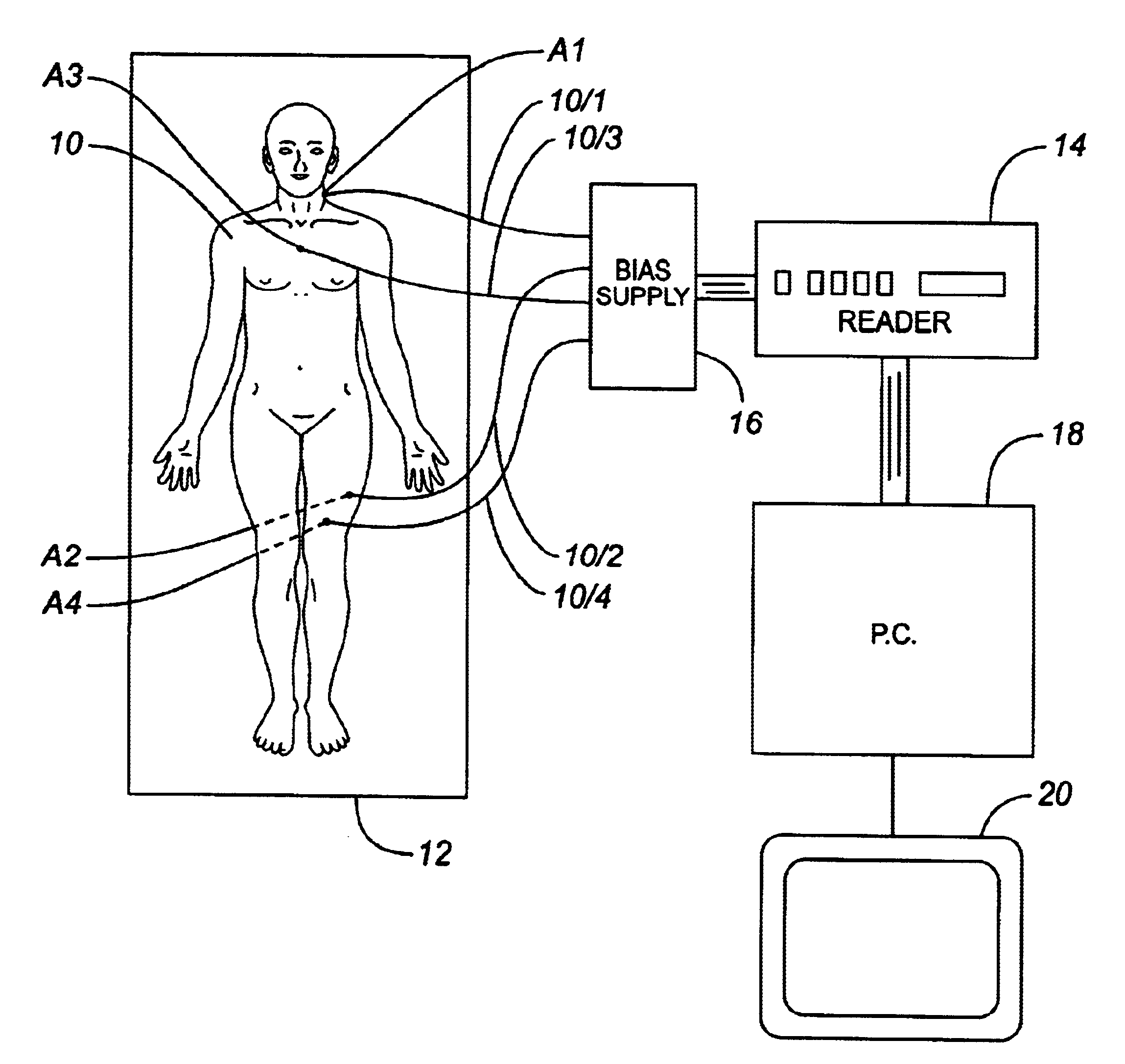
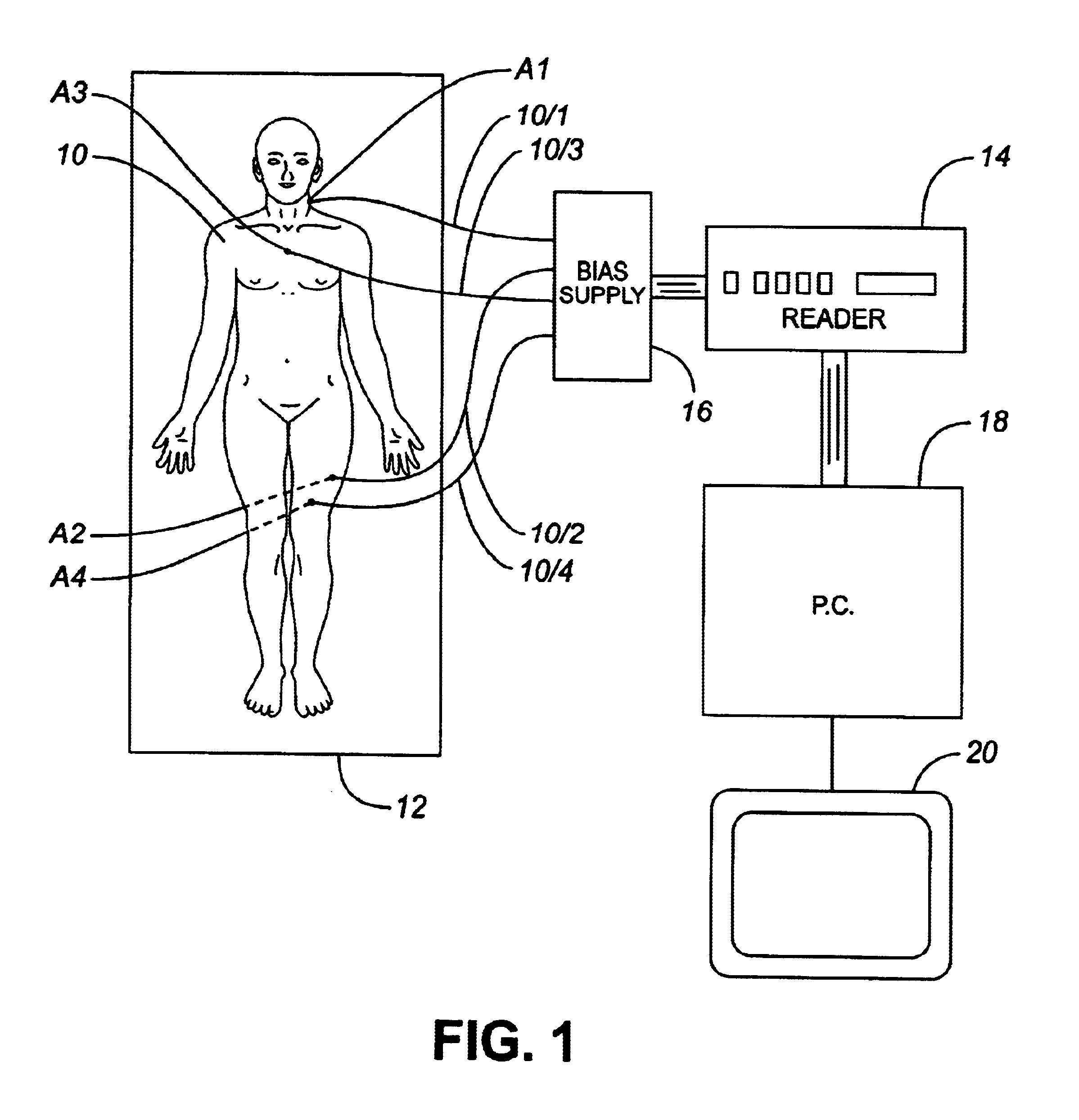
An object of the present invention is to at least mitigate this disadvantage and to this end, there is provided a dosimetry system having means for displaying a representation of the body, e,g., a patient, to be irradiated, showing specific locations of radiation sensors in relation to the body.
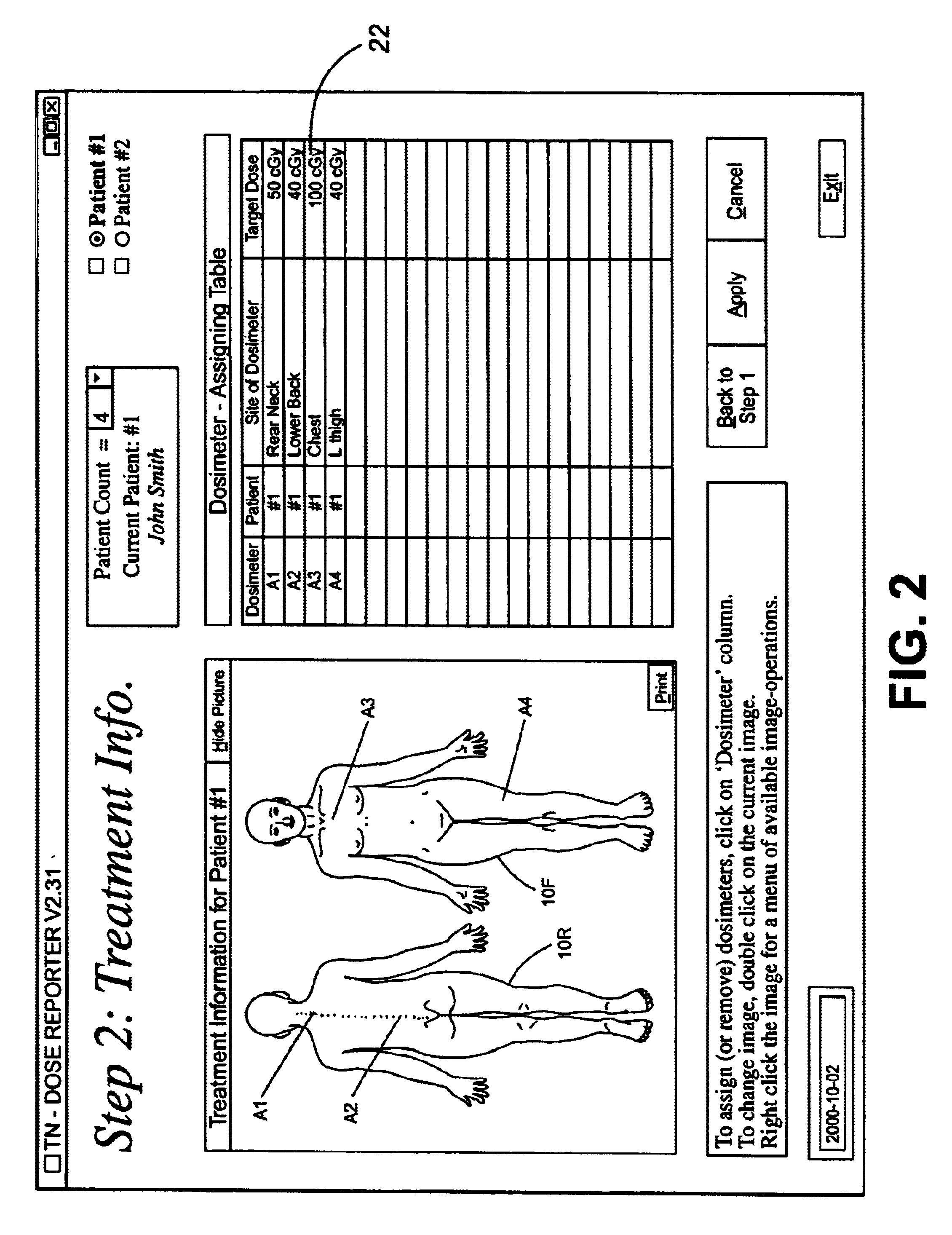
Preferably, the display system provides for adjustment of the sensor location artefacts prior to the irradiation, to select desired locations, and then may provide for printing of the representations, showing the sensor location artefacts, prior to irradiation, thus allowing the print-out to be used by an operator as a guide when positioning the sensors.
Yet another advantageous feature is that the one or more representations of the body, together with the preselected dosimeter sensor locations, may be printed prior to patient treatment so as to facilitate correct positioning of the dosimeter sensors in the correct anatomical positions by the medical personnel performing the radiotherapy procedure.
Another advantageous feature is that the patent's treatment information may be readily recorded (e.g. patient's name, identification of radiotherapy machine used, energy of the machine).
Another advantageous feature of embodiments of the present invention which use a computer display is that the software may calculate the radiation dose using the data input from the reading instrument and any calibration or correction factors previously input by the physicist, typically following a previous calibration of the dosimetry system in a known manner. The software then may compare the dose calculations with predetermined target doses and indicate, conveniently by highlighting in the display, any deviation for corrective action.

Problems solved by technology

A disadvantage of these known systems is that it is not easy to confirm that the dose values measured were taken at the proper locations on the body of the patient.

Method used


Image

  • Computer assisted radiotherapy dosimeter system and a method therefor
  • Computer assisted radiotherapy dosimeter system and a method therefor
  • Computer assisted radiotherapy dosimeter system and a method therefor

Examples


Embodiment Construction

A dosimetry system for monitoring the amount of radiation to which a patient is subjected will be described with reference to FIG. 1 which illustrates a patient 10 who is to receive radiation therapy while lying on a table 12. The therapy entails irradiating the patient 10 by means of a radiation therapy machine, which might be an X-ray machine, a CT scanner, or other machine having means (not shown) for irradiating the patient. The dosimetry system comprises a set of MOSFET radiation sensors A1 . . . A4 positioned at predetermined locations on the patient's body and connected by leads 10 / 1 . . . 10 / 4, respectively, to a reader 14 (e.g. Thomson & Neilsen's reader, Model No. 50 [TN-RD-50]) by way of a bias supply unit 16. The reader 14 is connected to a personal computer 18 which controls a display device 20. The sensors A1-A4, bias supply 16, reader 14 and computer 18 may be of known construction and so will not be described in detail. The personal computer 18 is equipped with the s...


PUM


Abstract

In order to facilitate the display and evaluation of data acquired while irradiating a body, e.g. a patient undergoing radiation therapy, a dosimetry system has a plurality of sensors for disposition on, in or near the body to be irradiated and connected to a sensor reading instrument which is interfaced with a display system, for example a personal computer, which is arranged to display, in use, one or more representations, for example drawings or photographs, of the body to be irradiated, along with the positions and the dose data for those specific locations where the dosimeter sensors were placed.

Description

The invention relates to radiotherapy dosimeter systems, especially of the kind which use a plurality of dosimeter sensors distributed in a region to be irradiated and means for monitoring radiation levels detected by the sensors.Radiotherapy treatment of cancer patients involves the use of machines which produce high energy X-rays or high energy electrons. It is common practice to verify the radiation dose delivered to the patient with a dosimetry system such as the Thomson & Nielsen Patient Dose Verification System.There are three different types of dosimetry system used in radiotherapy. These are based on (a) film or thermal luminescent dosimeters (TLD), (b) diodes and (c) MOSFETs. Diode and MOSFET systems use electronic dosimeter sensors together with electronic reading systems, whereas film or TLD use chemical or thermal methods of reading the detectors into an electronic reading system.Since diode and MOSFET based dosimetry systems have the convenience of direct electronic rea...

Claims


Application Information

Patent Timeline
Patent Type & Authority Patents(United States)
IPC IPC(8): A61N5/10
CPCA61N5/1048Y10S128/92A61N5/1071A61N2005/1074
Inventor DING, WEI
Owner BEST THERATRONICS
Learn More