Network relay device for relaying data in a network and control method for the same

a network and relay technology, applied in data switching networks, instruments, frequency-division multiplexes, etc., can solve the problems of not accurately identifying whether the failure occurring in the master switch is total failure or partial failure, the failure of the entire master switch or the occurrence of failures, and the failure of the direct lin

Active Publication Date: 2010-09-07
ALAXALA NETWORKS
View PDF7 Cites 174 Cited by
  • Summary
  • Abstract
  • Description
  • Claims
  • Application Information

AI Technical Summary

Benefits of technology

[0042]The other objects, features, structures, and effects of the invention as well as those discussed above will become more apparent through description of the embodiments.
[0043]The technique of the invention is not restricted to the above network relay devices but is also applicable to control methods of the network relay devices. There are other diverse applications of the invention, for example, computer programs to establish the network relay devices and their control methods, recording media in which such computer programs are recorded, and data signals that include such computer programs and are embodied in carrier waves.

Problems solved by technology

In the event of failure occurring on at least the direct link, the Backup switch detects the occurrence of failure on the direct link but can not accurately identify whether the failure occurring in the Master switch is total failure or partial failure.
The total failure in the Master switch represents the full malfunction of the whole Master switch or the occurrence of failures in all the lines connected to the Master switch.
The partial failure in the Master switch represents the occurrence of failure on the direct line and the occurrence of failure in at least one of the lines connected to the Master switch other than the direct link.
The total failure in the Master switch disables data communication by all the lines connected to the Master switch.
The partial failure in the Master switch, however, enables data communication by at least one of the lines connected to the Master switch other than the direct link.
The data communication by these two L2 switches both set in the Master operating status undesirably causes a loop in the network.
In the event of total failure occurring in the Master switch, on the other hand, all the lines connected to the Master switch are incapable of data communication.
Both the L2 switches disable data transmission and thus interrupt data communication in the network.

Method used


Image

  • Network relay device for relaying data in a network and control method for the same
  • Network relay device for relaying data in a network and control method for the same
  • Network relay device for relaying data in a network and control method for the same

Examples


first embodiment

B-1. First Embodiment

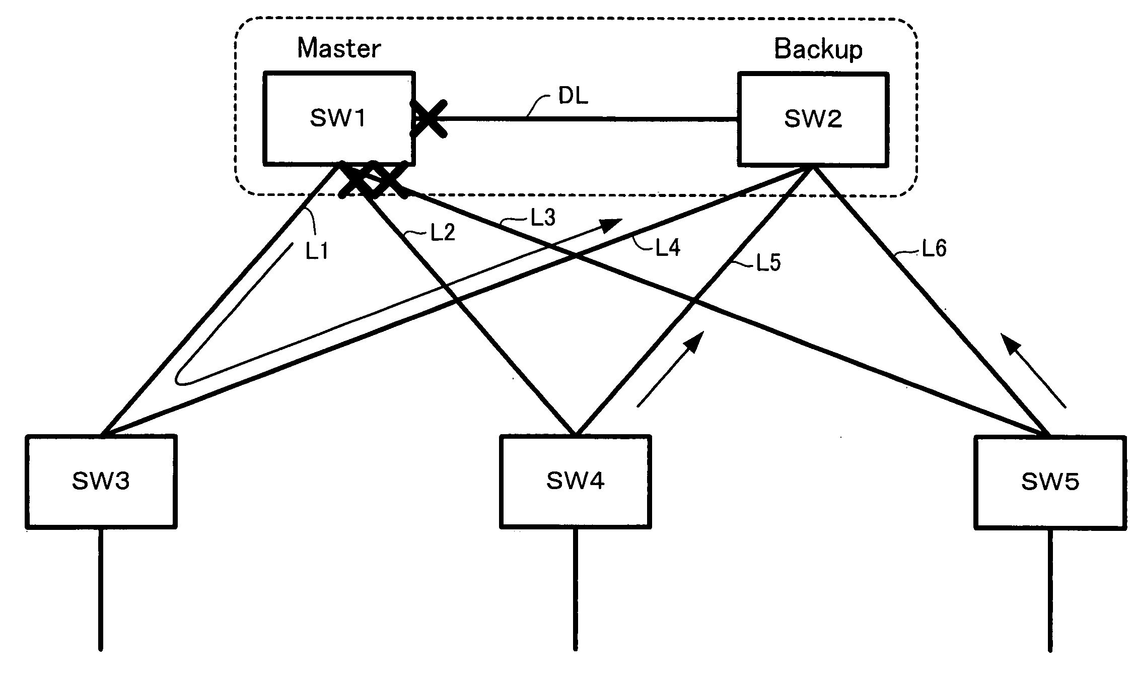
[0081]In the configuration of the first embodiment, all the downstream switches are the function-equipped switches SW3 to SW5. On the start of the operations of the upstream switches SW1 and SW2, the control modules 110-SW1 and 110-SW2 refer to the setting information and identify the types of the respective downstream switches linked to the ports of the upstream switches SW1 and SW2 by the lines L1 to L6. In the first embodiment, the control modules 110-SW1 and 110-SW2 identify connection of three function-equipped switches and no functionless switch as the downstream switches.

[0082]During the operations, the Master upstream switch SW1 and the Backup upstream switch SW2 exchange control messages at regular intervals via the direct link DL to verify the mutual survivals. In the event of partial failure occurring in the Master upstream switch SW1 including a direct link failure, the control module 110-SW2 of the Backup upstream switch SW2 detects the failure on t...

second embodiment

B-2. Second Embodiment

[0096]In the configuration of the second embodiment, the downstream switches include the function-equipped switches SW3 and SW5 and the functionless switch SW4′. On the start of the operations of the upstream switches SW1 and SW2, the control modules 110-SW1 and 110-SW2 refer to the setting information and identify the types of the respective downstream switches linked to the ports of the upstream switches SW1 and SW2 by the lines L1 to L6. In the second embodiment, the control modules 110-SW1 and 110-SW2 identify connection of two function-equipped switches and one functionless switch as the downstream switches.

[0097]During the operations, in the event of partial failure occurring in the Master upstream switch SW1 including a direct link failure, the control module 110-SW2 of the Backup upstream switch SW2 detects the failure on the direct link DL and starts a failure action control process shown in the flowchart of FIG. 6.

[0098]FIG. 6 is a flowchart showing t...

third embodiment

B-3. Third Embodiment

[0113]In the configuration of the third embodiment, all the downstream switches are the functionless switches SW3′ to SW5′. On the start of the operations of the upstream switches SW1 and SW2, the control modules 110-SW1 and 110-SW2 refer to the setting information and identify the types of the respective downstream switches linked to the ports of the upstream switches SW1 and SW2 by the lines L1 to L6. In the third embodiment, the control modules 110-SW1 and 110-SW2 identify connection of no function-equipped switch and three functionless switches as the downstream switches.

[0114]During the operations, in the event of partial failure occurring in the Master upstream switch SW1 including a direct link failure, the control module 110-SW2 of the Backup upstream switch SW2 detects the failure on the direct link DL and starts a failure action control process shown in the flowchart of FIG. 9.

[0115]FIG. 9 is a flowchart showing the failure action control process execu...


PUM


Abstract

In the case of detection of failure on a direct link interconnecting Master and Backup upstream switches, a control module of the Master upstream switch sends a partial failure message representing the occurrence of partial failure in the Master upstream switch via any of multiple lines connected to multiple ports of the Master upstream switch to the Backup upstream switch. Upon reception of the partial failure message from the Master upstream switch, a control module of the Backup upstream switch identifies partial failure occurring in the Master upstream switch and keeps the Backup operating status of the Backup upstream switch. Upon no reception of the partial failure message from the Master upstream switch, on the other hand, the control module of the Backup upstream switch identifies total failure occurring in the Master upstream switch and switches over the operating status of the Backup upstream switch from Backup to Master. In the event of failure occurring in the Master upstream switch, this arrangement effectively prevents unintentional interruption of data communication but ensures normal data communication in a network without causing the double-master state and the control loop in the network.

Description

[0001]The present application claims priority from Japanese application JP2005-242001 filed on Aug. 24, 2005, the content of which is hereby incorporated by reference into this application.BACKGROUND OF THE INVENTION[0002]1. Field of the Invention[0003]The present invention relates to a network relay device that relays data in a network.[0004]2. Description of the Related Art[0005]Networks generally adopt the policy of redundancy to prevent the unintentional stop of the functions in the whole network due to some failures occurring on lines and respective devices.[0006]Layer 2 (data link layer) and Layer 3 (network layer) in an OSI reference model have some differences in network characteristics. In Internet Protocol (IP) as a typical example of Layer 3, data communication is disabled between devices interconnected via a line, unless IP addresses are allocated to the respective devices. In Ethernet (registered trademark) as a typical example of Layer 2, data communication is enabled ...

Claims


Application Information

Patent Timeline
Patent Type & Authority Patents(United States)
IPC IPC(8): G06F11/07H04L12/46H04L45/586
CPCH04L49/351H04L49/552H04L49/557H04L69/40
Inventor ARAI, MASAYANOZAKI, SHINJIMIYAMOTO, TAKAHISA
Owner ALAXALA NETWORKS
Why Eureka
Try Eureka