Fuel assembly and plug-in distance element

a technology of fuel assembly and plug-in distance element, which is applied in the field of nuclear engineering, can solve the problems of increasing the degree of mixing of coolant flow along the length of the fuel assembly with decreasing hydraulic resistan

Active Publication Date: 2010-09-07
OTKRYTOE AKTSIONERNOE OBSCHESTVO TVEL +1
View PDF32 Cites 4 Cited by
  • Summary
  • Abstract
  • Description
  • Claims
  • Application Information

AI Technical Summary

Benefits of technology

[0017]The objective of this invention is to develop and provide a fuel assembly and an insertable spacing element (insert) having improved characteristics.
[0018]The achievement of this objective enables to obtain technical effects in overall improvement of the cell stiffness and, at the same time, bending of fuel rods along a fuel assembly is reduced, as well as hydraulic resistance to a coolant flow is decreased and, at the same time, a degree of mixing a coolant flow between adjacent cells in a fuel assembly is increased; contact pressure on the fuel rod surface is reduced which means lower fretting wear of fuel rods.
[0025]The said positive technical effects are also achieved due to the fact that an insertable spacing element is provided, which comprises a shell having cross section of octagon formed by four facets that are rounded and convex in the direction from the center of said element and by four facets located therebetween that are shaped and concave toward the center of the said element, said convex facets being designed for connection to a spacing grid cell and said concave facets being designed for fixing a fuel rod, wherein said concave facets have a straight section in their central parts.
[0027]In the result, the spacing element according to this invention has the following advantages over the known insertable element:
[0028]as compared to surfaces that are convex toward the fuel rod axis, the flat facets of the inventive insertable element create contact pressure that is several times less, which reduces the risk of excessive damage to the fuel rod surface and decreases possibility and rate of fretting wear in operation;
[0029]unlike a convex surface, the flat surface of the inventive insertable element ensures its spring properties enabling to compensate differences in geometry, misalignment of the axes of the fuel rod and the insertable element and maintain acceptable forces created while passing the fuel rod through a spacing grid when they are assembled tightly.

Problems solved by technology

In the result, the degree of mixing a coolant flow along the length of a fuel assembly is increased with decreasing hydraulic resistance.

Method used


Image

  • Fuel assembly and plug-in distance element
  • Fuel assembly and plug-in distance element
  • Fuel assembly and plug-in distance element

Examples


Embodiment Construction

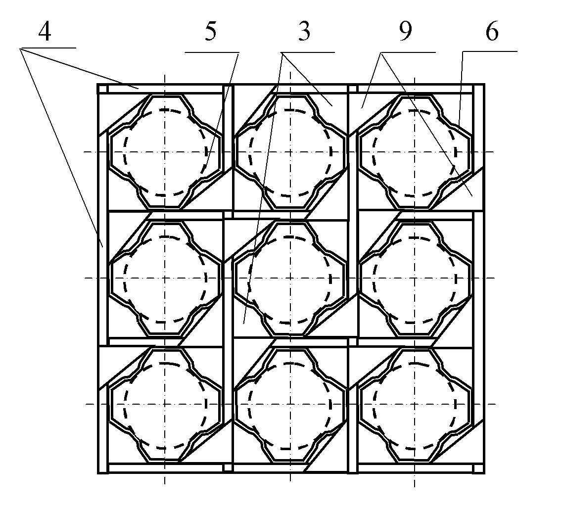
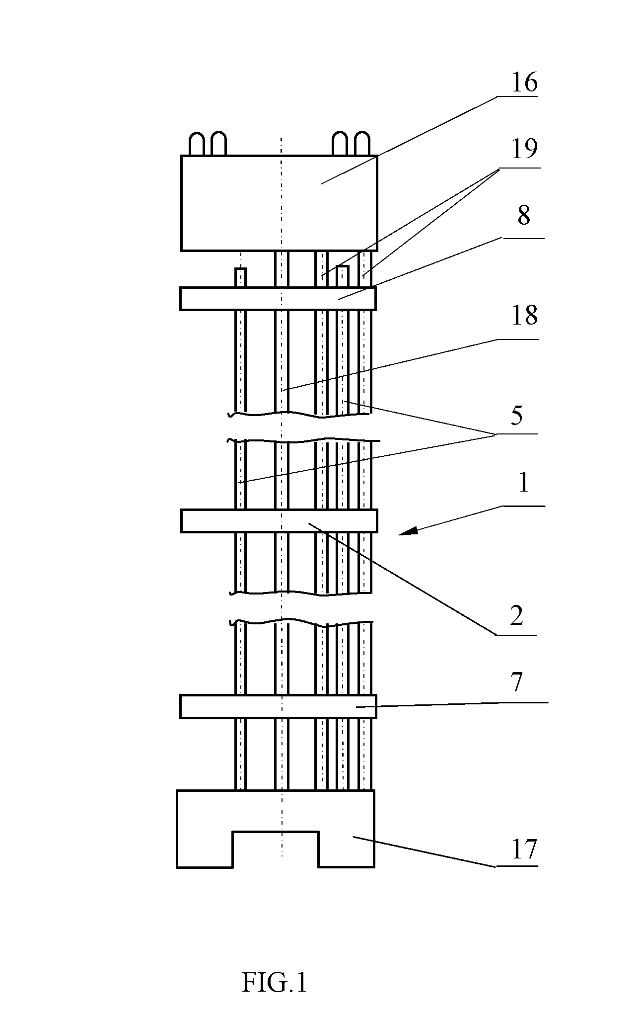
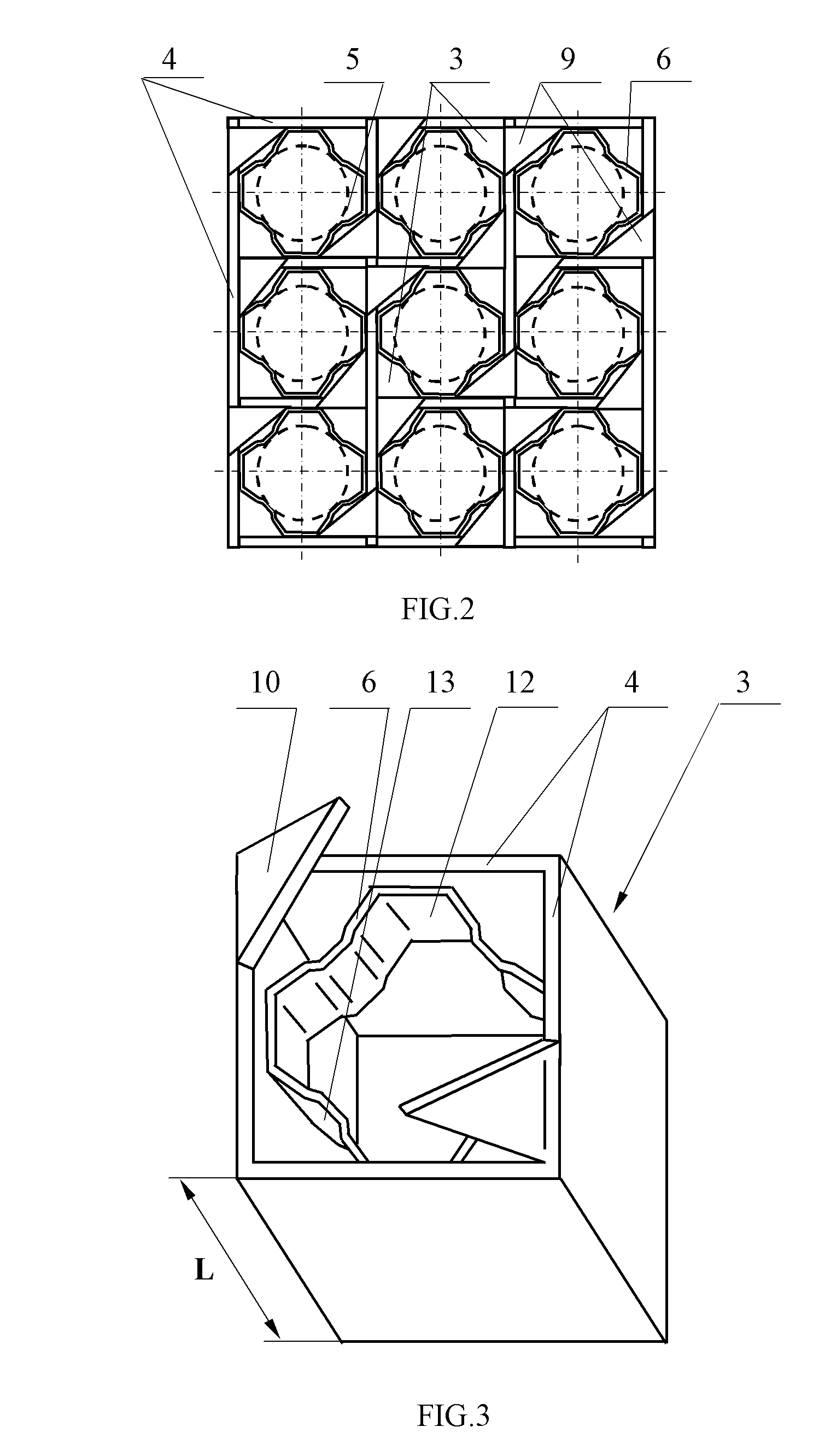
[0039]A fuel assembly 1 comprises spacing grids 2 that are arranged along the length of the assembly 1 downstream a coolant flow. The spacing grids 2 comprise cells 3 formed by orthogonal crossing plates 4. Each cell 3, through which a fuel rod 5 passes, has an insertable spacing element 6 embracing the fuel rod 5 and designed for fixing the fuel rod 5 passing through the cell 3. In the spacing grids that are arranged between the first spacing grid 7 and the last spacing grid 8 downstream the coolant flow at least some cells 3, through which the fuel rods 5 pass, are provided with deflectors 9 designed for mixing the coolant flow. The deflectors 9 are made on the crossing plates 4 in the form of bent vanes 10. The length L of a cell 3 in the direction of its longitudinal axis is selected in the range from 15 mm to 60 mm. A size of the insertable spacing element 6 along the length L of a cell is in the range from 5 mm to 20 mm. The insertable spacing element 6 has a closed contour an...


PUM


Abstract

This invention relates to nuclear engineering and may be used in structures of nuclear fuel assemblies, especially those used in PWR and BWR nuclear reactors. A fuel assembly comprises spacing grids comprising cells formed by orthogonal crossing plates. An insertable spacing element is installed in each cell, which is designed for fixing the fuel rod passing through the cell. In the spacing grids that are arranged between the first spacing grid and the last spacing grid downstream the coolant flow at least some cells, through which the fuel rods pass, are provided with deflectors designed for mixing the coolant flow. The insertable spacing element comprises a shell, which has a cross-section in the form of an octagon formed by four facets that are rounded and convex in the direction from the center of said element and by four facets located therebetween that are shaped and concave toward the center of the said element. The result is that cell stiffness is increased, and hydraulic resistance to a coolant flow is reduced.

Description

FIELD OF THE INVENTION[0001]This invention relates to nuclear engineering and may be used in structures of nuclear fuel assemblies formed of a bundle of fuel rods that are spaced and fixed in spacing grids, in particular in fuel assemblies for PWR and BWR reactors wherein fuel rods are arranged according to a square pattern.PRIOR ART[0002]In order to ensure a required spacing between fuel rods during the whole life of a fuel assembly spacing grids are used that also fix fuel rods in pressed positions for the purpose of excluding fretting wear of fuel rod cladding materials. Cells of spacing grids may be formed, in particular, by orthogonal crossing plates or by pressing from tube blanks and connecting them therebetween and with a surrounding rim by welding or soldering.[0003]In order to eliminate cross overflows between fuel assemblies their spacing grids should have close hydraulic characteristics and be located at similar levels.[0004]In order to prevent spacing grids of abutting ...

Claims


Application Information

Patent Timeline
Patent Type & Authority Patents(United States)
IPC IPC(8): G21C3/34
CPCG21C3/322G21C3/344G21C3/352G21Y2002/201G21Y2004/30Y02E30/31Y02E30/32Y02E30/38Y02E30/30
Inventor ROZHKOV, VLADIMIR VLADIMIROVICHLAVRENYUK, PETR IVANOVICHKISLITSKY, ALEKSANDR ANTONOVICHTROYANOV, VLADIMIR MIKHAILOVICHENIN, ANATOLY ALEKSEEVICHSHUSTOV, MSTISLAV ALEKSANDROVICHUSTIMENKO, ALEKSANDR PAVLOVICHNEKHODA, MIKHAIL MIKHAILOVICHSAMOILOV, OLEG BORISOVICHDOLGOV, ALEKSEY BORISOVICH
Owner OTKRYTOE AKTSIONERNOE OBSCHESTVO TVEL
Why Eureka
Try Eureka