Transfer tool

a technology of transfer tape and tool, which is applied in the field of transfer tape, can solve the problems of generating labor for rewinding the transfer tape, damage to the stopper member exposed outside the refill, and unnecessary rotation of the supply reel or the winding reel

Active Publication Date: 2010-09-14
KOKUYO CO LTD
View PDF9 Cites 9 Cited by
  • Summary
  • Abstract
  • Description
  • Claims
  • Application Information

AI Technical Summary

Benefits of technology

[0008]With this, it is possible to prevent the supply reel or the winding reel from being rotated due to a friction force generated between the supply reel and the stopping member disposed in the inserting position and a friction force generated between the stopping member and the support plate when the refill is alone put into circulation. That is, the unnecessary rotation of the supply reel or the winding reel when the refill is alone put into circulation can reliably prevented by the small stopping member. The stopping member is inserted between the supply reel and the support plate or between the winding reel and the support plate. Thus, it is unnecessary to change the design of other than the refill, and the number of portions having the common designs with respect to the conventional transfer tool can be increased.
[0009]To more reliably suppress the unnecessary rotation of the supply reel or the winding reel by the stopping member, the transfer tool may includes a stopping member holding portion which holds the stopping member in the inserting position.
[0010]As one mode capable of realizing the stopping member holding portion with a simple structure, a projection is provided on one of the stopping member and the support plate, a recess is formed in the other one of the stopping member and the support plate, and the stopping member holding portion engages the projection and the recess each other. According to this mode, a special part for retaining the stopping member in the inserting position is not required, and the number of parts is not increased.
[0012]In order to prevent an inconvenience such as cut of the transfer tape from occurring when the transfer tool which includes a pair of first and second cases capable of relatively moving between the use position and the open position, is used in the state that the supply of the transfer tape from the supply reel is restrained after the cases are moved to the use position in remaining the stopping member disposed in the inserting position, the stopping member includes a plate-like body which can be inserted in between the supply reel and the support plate or in between the winding reel and the support plate, and a knob projecting from one end of the body, and when the stopping member is disposed in the inserting position and the first and second cases relatively move, one of the cases abuts against the knob to limit further movement thereof toward the use position.
[0013]According to the structure of the transfer tool of the present invention, it is possible to prevent the supply reel or the winding reel from being rotated due to a friction force generated between the supply reel and the stopping member disposed in the inserting position and a friction force generated between the stopping member and the support plate when the refill is alone put into circulation. That is, the unnecessary rotation of the supply reel or the winding reel when the refill is alone put into circulation can reliably prevented by the small stopping member. The stopping member is inserted between the supply reel and the support plate or between the winding reel and the support plate. Thus, it is unnecessary to change the design of other than the refill, and the number of portions having the common designs with respect to the conventional transfer tool can be increased.

Problems solved by technology

Here, if the stopping member is made of thick paper, a portion of the stopping member exposed outside of the refill is damaged due to impact received during transportation, the supply reel or the winding reel rotates unnecessarily, and a labor for rewinding the transfer tape is generated in some cases.
Further, when the refill is provided with the stopping means, it is necessary to provide the case with a releasing-engaging portion that can engage the stopping-releasing portion of the stopping means, and it is difficult to commonly design the conventional refill and case.

Method used


Image

  • Transfer tool
  • Transfer tool
  • Transfer tool

Examples


Embodiment Construction

[0024]An embodiment of the present invention will be explained with reference to the drawings.

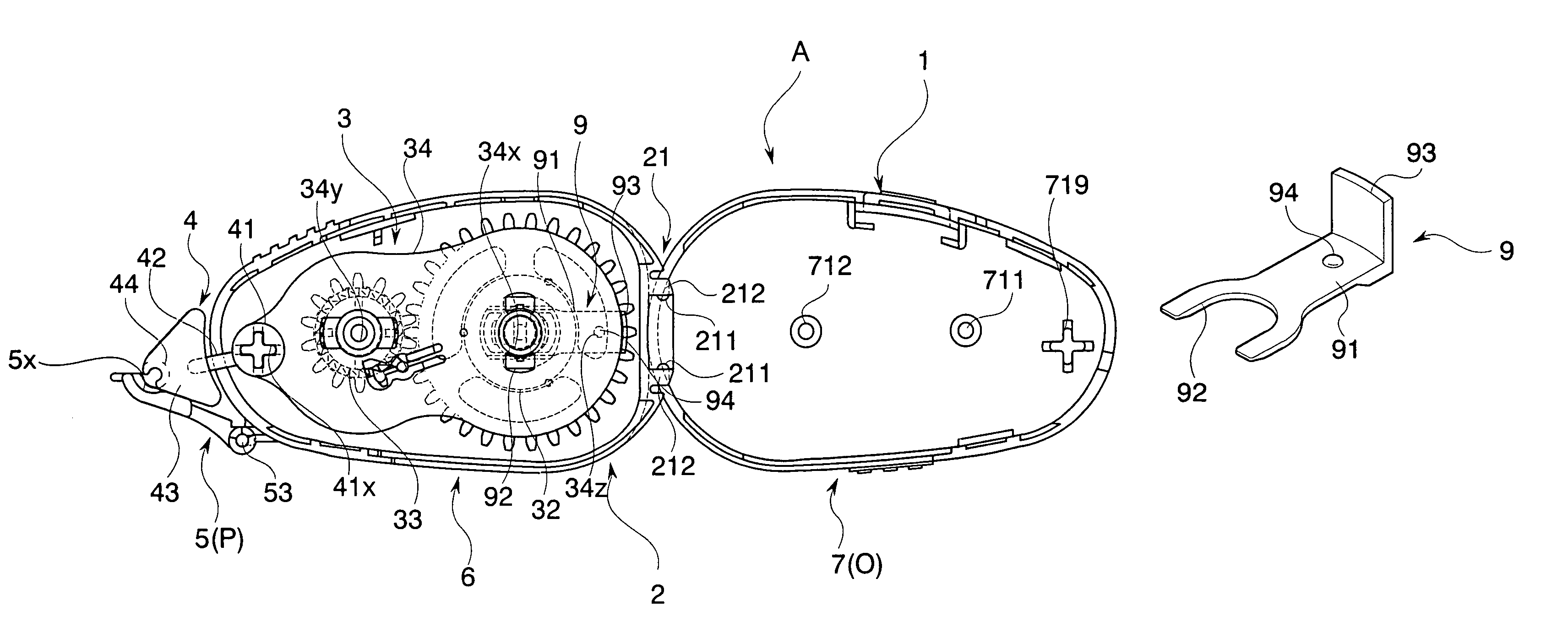
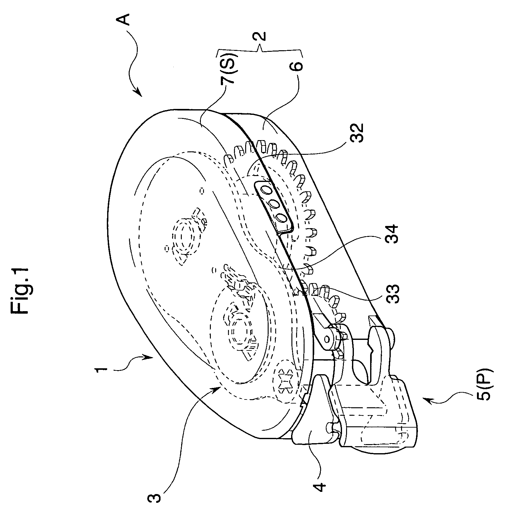
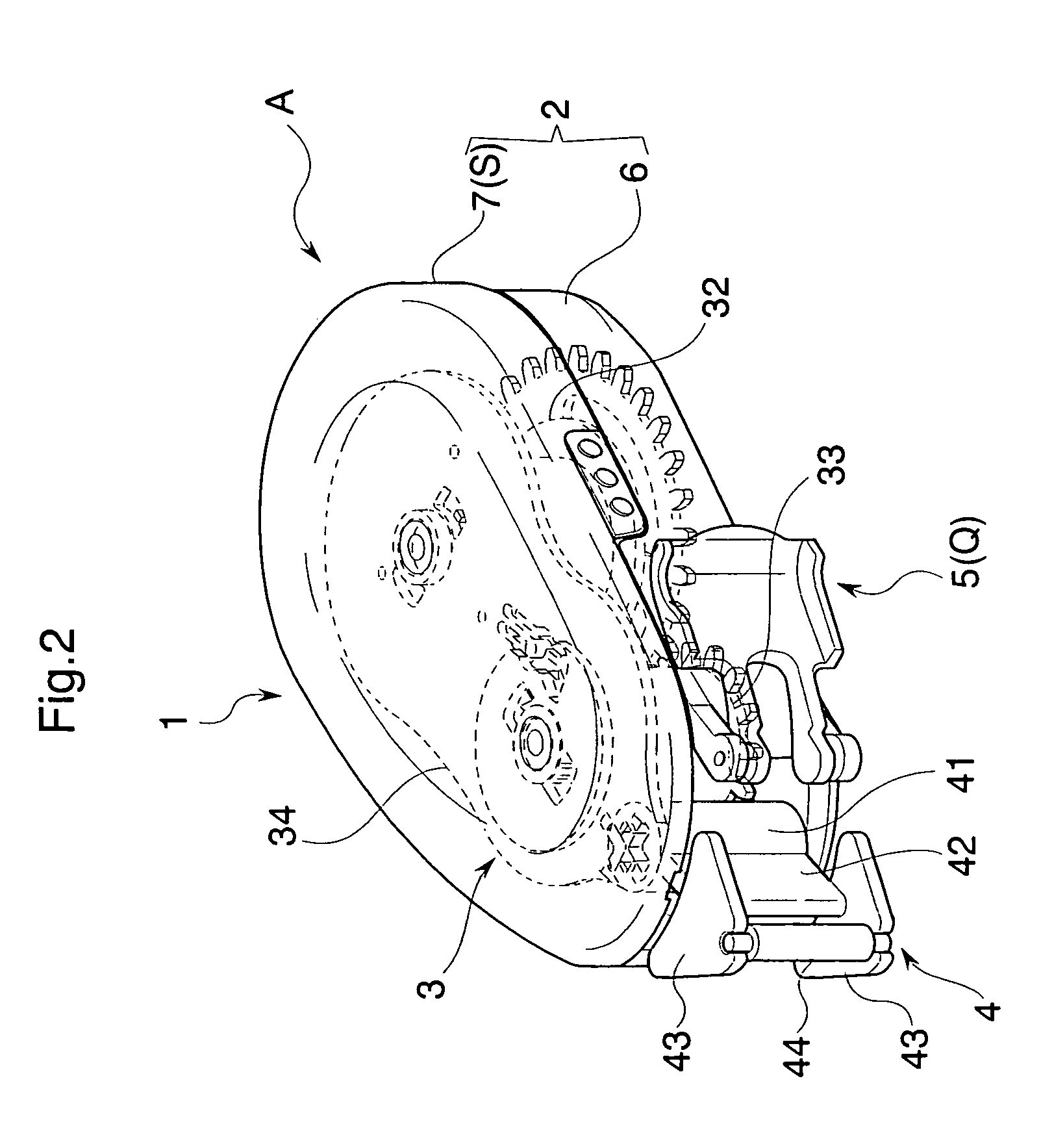
[0025]As shown in FIGS. 1 to 5, a transfer tool A according to the embodiment includes a transfer tool body 1 having a case portion 2 and a refill 3 which can hold the case portion 2, a transfer head 4 which is held by the transfer tool body 1, more specifically by the refill 3, and a head cap 5 which is pivotally attached to the transfer tool body 1, more specifically to the case portion 2. FIG. 1 is a perspective view of a state where the head cap 5 of the transfer tool A is disposed in a later-described close position P. FIG. 2 is a perspective view of a state where the head cap 5 of the transfer tool A is disposed in a later-described open position Q. FIG. 3 is an exploded perspective view of the transfer tool A. FIG. 4A is a side view of the transfer tool A, FIG. 4B is a bottom view of the transfer tool A, and FIG. 4C is a vertical sectional view taken along the center of the transfer ...


PUM


Abstract

The present invention provides a transfer tool comprising a refill which has a supply reel and a winding reel around which a transfer tape is wound and which hold the transfer tool, and a support plate which rotatably supports the supply reel and the winding reel, a stopping member is provided between the supply reel and the support plate such that the stopping member can be inserted and pulled out, and rotation of the supply reel or the winding reel is suppressed when the stopping member is disposed at a predetermined inserting position.

Description

BACKGROUND OF THE INVENTION[0001]1. Field of the Invention[0002]The present invention relates to a transfer tool having a refill including a supply reel and a winding reel around which a transfer tape is wound and which holds the transfer tape, and a support plate which rotatably supports the supply reel and the winding reel.[0003]2. Background of the Related Art[0004]Conventionally, there is widely used a transfer tool having a refill including a supply reel and a winding reel around which a transfer tape is wound and which holds the transfer tape, and a support plate which rotatably supports the supply reel and the winding reel, in which the refill is detachably attached to a case. In such a transfer tool, since the refill can be replaced when the entire transfer tape is wound around the winding reel, not only the refill attached to the case is in circulation, but a replacement refill is also in circulation widely. When the replacement refill is alone put into circulation, heretof...

Claims


Application Information

Patent Timeline
Patent Type & Authority Patents(United States)
IPC IPC(8): B65D85/02
CPCB65H37/007
Inventor KINUGASA, SHUJISHIMA, HIDETO
Owner KOKUYO CO LTD
Why Eureka
Try Eureka