System and method of multi-channel signal calibration

a multi-channel subsystem and multi-channel technology, applied in transmission systems, physical parameter compensation/prevention, instruments, etc., can solve the problems of significant compromise of multi-channel subsystem performance, high undesirable, and significant relative calibration errors between plurality of elements

Inactive Publication Date: 2010-09-14
RAZ GIL M
View PDF8 Cites 143 Cited by
  • Summary
  • Abstract
  • Description
  • Claims
  • Application Information

AI Technical Summary

Problems solved by technology

In particular, when the relationship between the individual elements of a multi-channel subsystem is improperly calibrated (e.g., with respect to their relative sample times, frequencies or locations), the performance of the multi-channel subsystem is significantly compromised, which is highly undesirable.
However, it has been found that since both of the aforementioned processes relate solely to single-channel corrections within a multi-channel subsystem, significant relative calibration errors often remain between the plurality of elements, which is highly undesirable.
As can be seen, the interleaved ADC is responsible for producing a number of sizable distortions D which significantly limit the overall dynamic range of the system, which is highly undesirable.
As can be seen, interleaved distortion product N significantly reduces the dynamic range of the interleaved ADC, which is highly undesirable.

Method used


Image

  • System and method of multi-channel signal calibration
  • System and method of multi-channel signal calibration
  • System and method of multi-channel signal calibration

Examples


Embodiment Construction

System and Method of Multi-Channel Signal Calibration

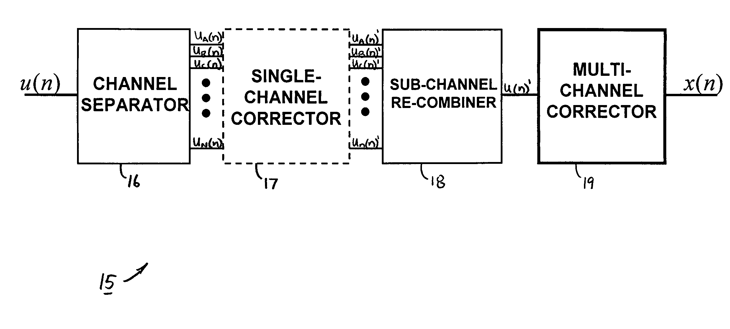
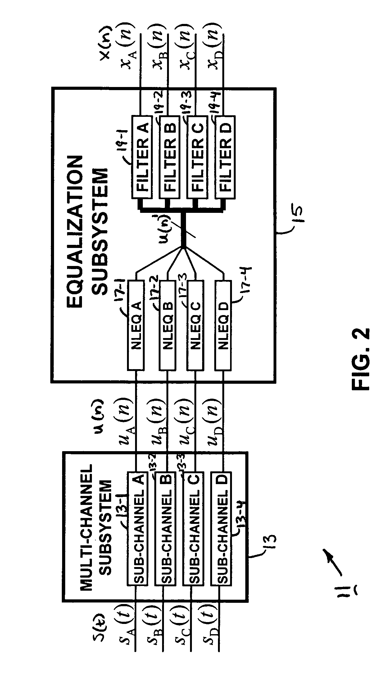
[0036]Referring now to FIG. 2, there is shown a simplified block diagram of a signal processing system constructed according to the teachings of the present invention and identified generally by reference numeral 11. As can be seen, system 11 comprises a multi-channel subsystem 13 which converts a set of analog input signals s(t) into an unequalized set of digitized output signals u(n) and an equalization subsystem 15 which is responsible for, inter alia, calibrating the distorted, complete-channel signal u(n) in such a manner so as to yield an equalized, complete-channel output signal x(n). As will be described in detail below, equalization subsystem 15 minimizes the presence of calibration errors produced by multi-channel subsystem 13 by calibrating the individual sub-channels of output signal u(n) relative to one another, which is highly desirable.

[0037]Multi-channel subsystem 13 represents any signal processing device which in...


PUM


Abstract

A signal processing system for reducing calibration-related distortions in a complete-channel signal generated by a multi-channel subsystem, such as an interleaved ADC, includes a channel separator for separating the distorted digital signal into its various sub-channels and a single-channel corrector for independently processing each sub-channel to reduce distortion products present therein. The system additionally includes a subchannel re-combiner for combining the plurality of sub-channels processed by the single-channel corrector and a multi-channel corrector for calibrating each of plurality of sub-channels relative to one another to yield an equalized, complete-channel output signal. The multi-channel corrector includes a bank of optimized filters, each filter being assigned to a corresponding sub-channel of the complete-channel signal. In one embodiment, one of the plurality of sub-channels is selected as an ideal reference signal and the filters assigned to the remaining sub-channels are optimized to yield outputs which match the ideal reference signal.

Description

CROSS-REFERENCE TO RELATED APPLICATIONS[0001]The present application claims the benefit under 35 U.S.C. 119(e) of U.S. provisional Patent Application Ser. No. 60 / 959,663, filed Jul. 16, 2007, the disclosure of which is incorporated herein by reference.BACKGROUND OF THE INVENTION[0002]The present invention relates generally to the field of digital signal processing and more particularly to systems and methods for calibrating multi-channel subsystems.[0003]In the field of analog and digital communications, a signal is commonly defined as anytime-varying or spatial-varying quantity that conveys information (e.g., an energy signal or power signal). Presently, there exists a wide variety of devices that are designed to process analog and / or digital signals in some capacity.[0004]To enhance its overall performance, signal processing systems often rely upon multi-channel subsystems. As defined herein, a multi-channel subsystem relates to a plurality of individual signal processing elements...

Claims


Application Information

Patent Timeline
Patent Type & Authority Patents(United States)
IPC IPC(8): H03M1/10
CPCH03M1/1033H03M1/1215
Inventor RAZ, GIL M.JACKSON, JEFFREY H.
Owner RAZ GIL M
Why Eureka
Try Eureka