Method and apparatus for detecting image movement

a technology of image movement and apparatus, applied in image analysis, instruments, computing, etc., can solve the problems of inability to detect errors, low location resolution, and multiple noise sources of frame detectors, so as to enhance the capability of detecting minor displacement, reduce calculation, and enhance the ability of detecting maximum displacement

Inactive Publication Date: 2010-09-14
SUNPLUS TECH CO LTD
View PDF12 Cites 8 Cited by
  • Summary
  • Abstract
  • Description
  • Claims
  • Application Information

AI Technical Summary

Benefits of technology

[0012]Accordingly, the present invention is directed to a method of detecting image movement. In the same reference frame, different reference windows can be dynamically captured in the direction reverse to the direction of the moving vector based on the previously detected frame. Accordingly, the detecting capability of single-direction maximum displacement can be enhanced. In addition, the capability of detecting minor displacement in various directions can also be improved so that the minor angle variation of the frame can be detected. When the detected frame displacement is larger than the maximum detectable displacement, the moving vector is compensated according to the principle of inertia.
[0013]The present invention is also directed to an apparatus for detecting image movement. For keeping the hardware structure simple and reducing the calculation, the present invention enhances the capabilities of detecting the maximum displacement and the minor displacement. Accordingly, the sensitivity of detecting the frame angle variation doubles that of the conventional technology.
[0015]Before the sampling window reaches the margin of the frame, in the same reference frame, different reference windows are dynamically captured in the reverse direction of the image movement vector according to the previously detected frame. Accordingly, the capability of detecting the maximum displacement is enhanced. In addition, the reference frame is not renewed until both the reference window and the sampling window have reached the margin of the frame. Accordingly, the capability of detecting minor displacement in horizontal and vertical directions is improved. The minor frame angle variation can be obtained by calculating the displacement in different directions. For example, in the 8×8 frame with 2×2 reference windows, the slope of the minimum moving angle detectable in the present invention is 0.5 / 6, i.e., about 4.8 degrees.
[0018]Accordingly, when detecting image movement, the present invention does not require additional hardware and can reduce the calculation, while enhancing the capability of detecting the maximum displacement. In addition, the present invention can enhance the capability of detecting the minor displacement to calculate the image movement angle variation. Moreover, when the detected frame displacement is more than the maximum detectable displacement, the moving vector is compensated according to the principle of inertia.

Problems solved by technology

Though the structure is simple, a mouse must be frequently cleaned to get rid of the accumulated dust, and also the low location resolution is another disadvantage.
In fact, the frame detector has several noise sources.
Detecting errors are unavoidable.
In the traditional technology, due to the restrictions of the frame detector size and the frame speed, the moving speed of the frame detector is limited.
When the moving speed of the frame detector is higher than the limit allowed for the hardware, the window having a gray level similar to that of the frame window cannot be captured by the block match method.
This will result in incorrect determination in the block match method, and the displacement of the frame detector cannot be correctly calculated.
Though increasing the maximum displacement, this method cannot enhance the moving angle detection.
As a result, a complex and great calculation is unavoidable.

Method used


Image

  • Method and apparatus for detecting image movement
  • Method and apparatus for detecting image movement
  • Method and apparatus for detecting image movement

Examples


Embodiment Construction

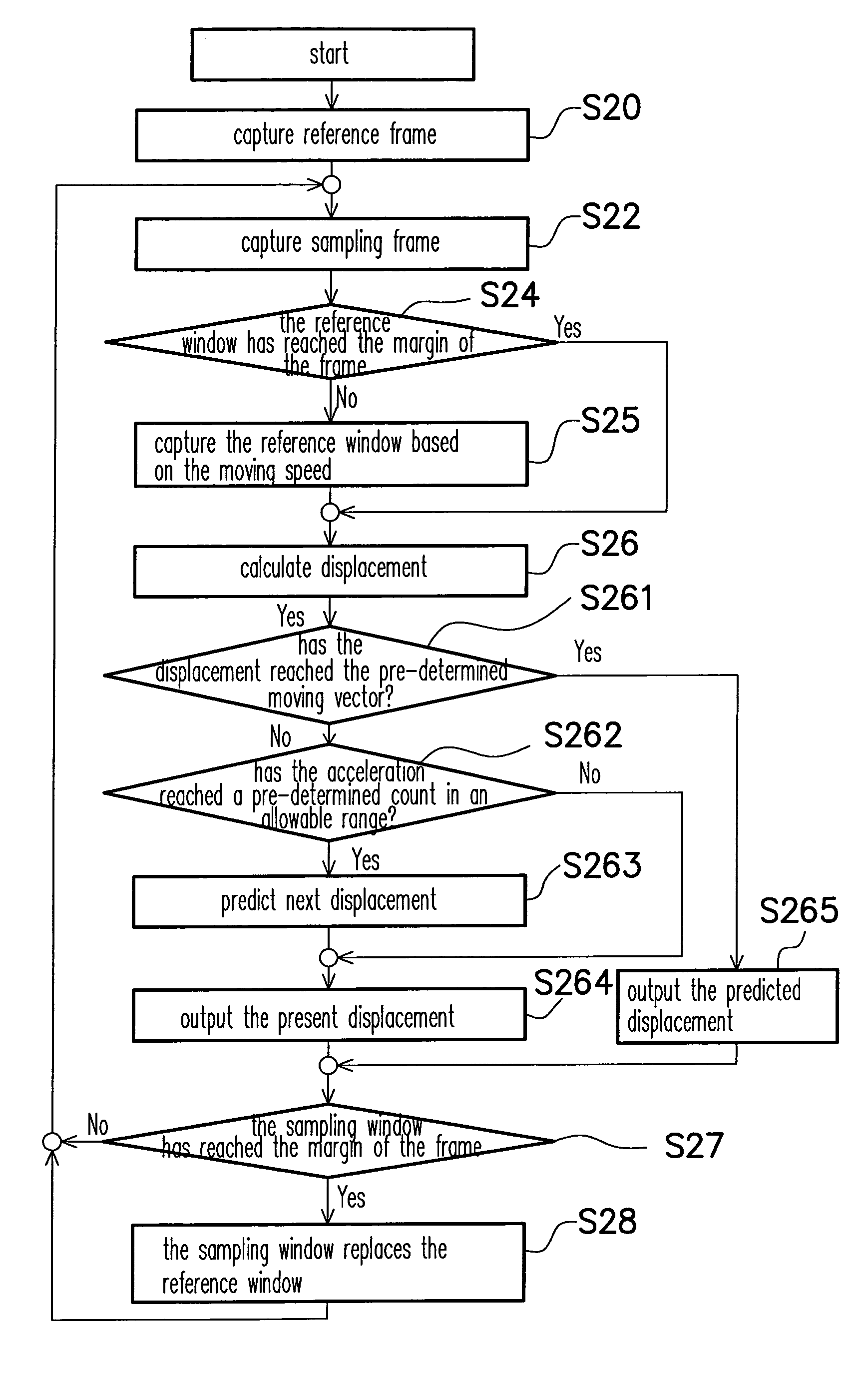
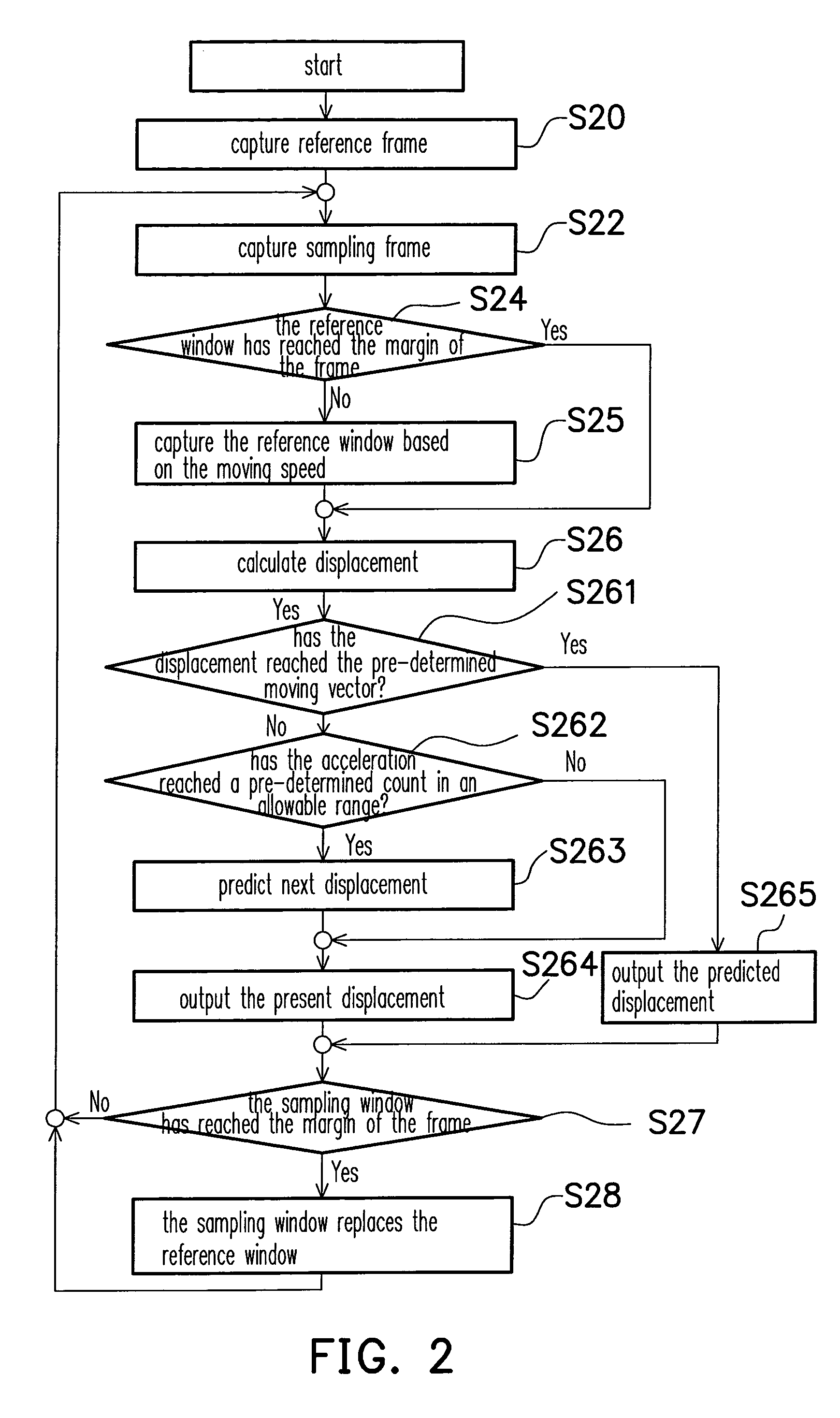
[0026]FIG. 2 is a flowchart showing a method of an embodiment of the present invention. FIGS. 3A-3F are drawings showing steps of detecting image movement according to an embodiment with a 8×8 frame of the present invention, wherein the left column represents reference frames, and the right column represents sampling frames. Referring to FIGS. 2, and 3A-3F, the value of the black squares is 0, and the value of the white squares is 8. The present invention can be applied to an apparatus which can detect the image movement, such as an optical mouse. In this embodiment, the mouse moves to the left and then upward. The moving angle is about 7 degrees, or ⅛, and the frame moves to the bottom right. In this embodiment of the present invention, the steps of detecting image movement are described below. In the step S20, a first frame is captured to serve as the reference frame 10. The center of the reference frame 10 is captured as the reference window 16. In the step S22, a second frame is...


PUM


Abstract

A method of detecting image movement is provided. A reference frame is accessed, and a reference window is captured from the reference frame. A sampling frame is then accessed. When the reference window has not reached the margin of the reference frame, a new window is captured from the reference frame to replace the reference window. From the reference frame, a window matching the reference window is searched and a moving vector is calculated. When the sampling window reaches the margin of the sampling frame, the sampling frame replaces the reference frame. Another reference window is also captured from the reference frame, and the step of accessing the sampling frame is repeated.

Description

CROSS-REFERENCE TO RELATED APPLICATION[0001]This application claims the priority benefit of Taiwan application serial no. 93140723, filed on Dec. 27, 2004. All disclosure of the Taiwan application is incorporated herein by reference.BACKGROUND OF THE INVENTION[0002]1. Field of the Invention[0003]The present invention relates to a method and an apparatus for detecting image movement, and more particularly to a method and an apparatus for detecting image movement capable of enhancing displacement and small angle detection.[0004]2. Description of the Related Art[0005]With the advance of computer functions, and development in internet and multi-media technology, image data are transmitted in the digital form, rather than in analog form. In order to meet the modern life style, peripheral apparatus of computers have developed to be slim, precisely controllable, and multi-functional. For example, a conventional mouse uses a ball to control the locations. Though the structure is simple, a m...

Claims


Application Information

Patent Timeline
Patent Type & Authority Patents(United States)
IPC IPC(8): G06F3/033
CPCG06F3/0317G06T7/20
Inventor CHOU, TSE-AN
Owner SUNPLUS TECH CO LTD
Why Eureka
Try Eureka