Calibration procedure for rivet height gages

a technology of height gages and calibration procedures, applied in the field of data processing systems, can solve the problems of improper fitting, difficult installation of rivets in holes, and inability to accurately calibrate rivet height gages, and achieve the effect of minimizing or eliminating the effect of roll-off and accurate calibration of rivet height gages

Inactive Publication Date: 2010-09-14
THE BOEING CO
View PDF4 Cites 8 Cited by
  • Summary
  • Abstract
  • Description
  • Claims
  • Application Information

AI Technical Summary

Benefits of technology

[0021]Thus, the advantageous embodiments provide a method and a sphere-based ring gage for calibrating rivet height gages while minimizing or eliminating the effects of roll-off and permitting a more accurate calibration of rivet height gages. The features, functions, and advantages can be achieved independently in various embodiments of the present disclosure or may be combined in yet other embodiments in which further details can be seen with reference to the following description and drawings.

Problems solved by technology

If a countersink for the rivet is the wrong size, shape, or is misaligned relative to the rivet hole or surrounding material, the rivet may be difficult to install in the hole, may fit up improperly, or may be preloaded in a non-optimal manner.
These conditions may be undesirable.
In such cases, the head of the fastener may protrude above the surrounding surface further than desired, sit at an incorrect angle, or sit too low in the countersink.
At aircraft speed, these protruding, misaligned, or too deep fastener heads may be undesirable.
The sharp edges on these rivet calibration gages may be subject to wear, smoothing, and rounding at the edges of the ring gage.
Moreover, the roll-off, also known as round-off, of the sharp edge on currently available rivet calibration gages may preclude a better rivet gage calibration.
However, roll-off removal may be difficult and time consuming.
Moreover, sharp-edges may frequently not be sharp enough even when the ring gage is new.
Therefore, current solutions may be insufficient to counter the effects of roll-off.

Method used


Image

  • Calibration procedure for rivet height gages
  • Calibration procedure for rivet height gages
  • Calibration procedure for rivet height gages

Examples


Embodiment Construction

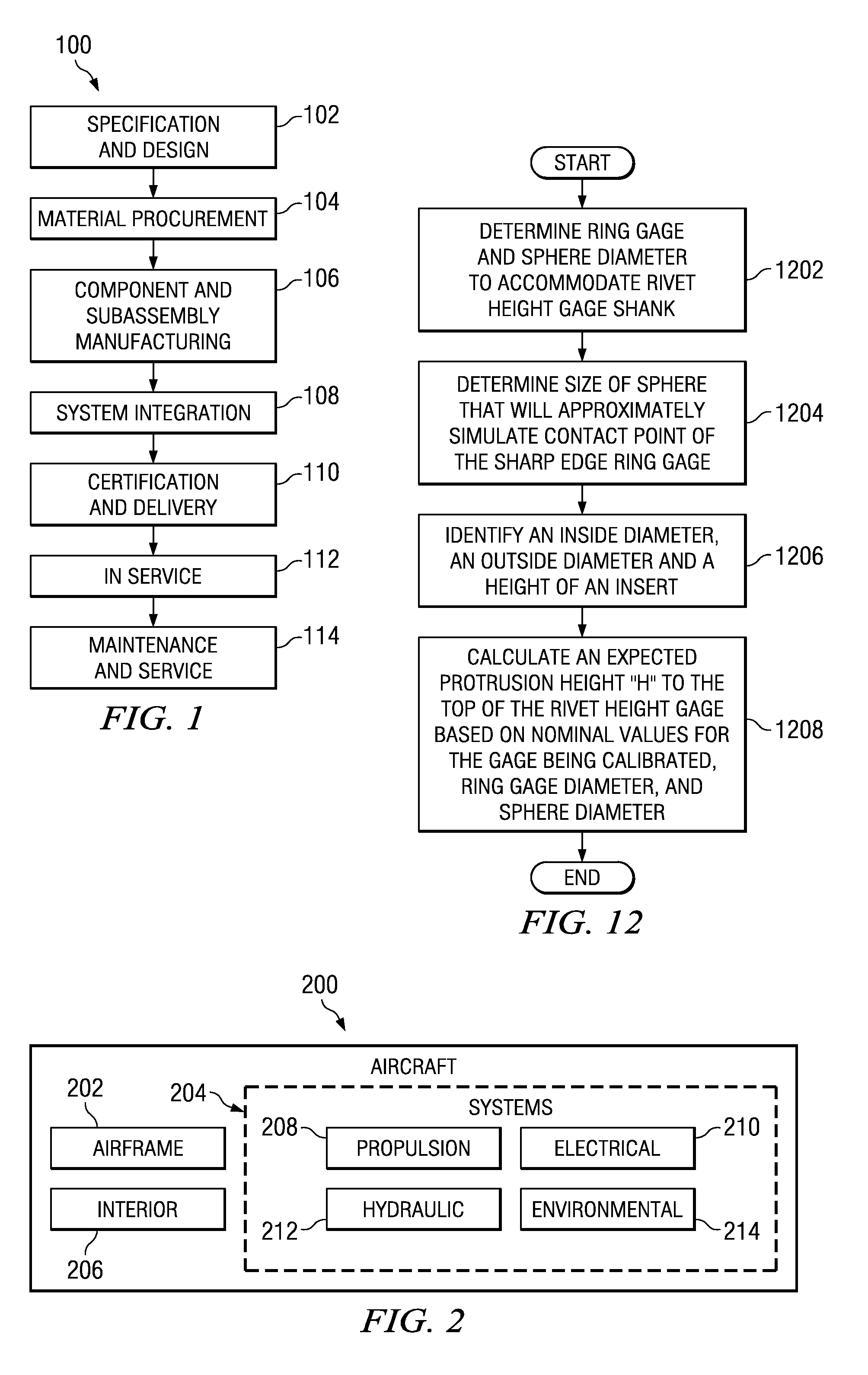
[0036]Referring more particularly to the drawings, embodiments of the disclosure may be described in the context of the aircraft manufacturing and service method 100 as shown in FIG. 1 and aircraft 200 as shown in FIG. 2. Turning first to FIG. 1, a diagram illustrating an aircraft manufacturing and service method is depicted in accordance with an advantageous embodiment. During pre-production, exemplary aircraft manufacturing and service method 100 may include specification and design 102 of aircraft 200 in FIG. 2 and material procurement 104. During production, component and subassembly manufacturing 106 and system integration 108 of aircraft 200 in FIG. 2 takes place. Thereafter, aircraft 200 in FIG. 2 may go through certification and delivery 110 in order to be placed in service 112. While in service by a customer, aircraft 200 in FIG. 2 is scheduled for routine maintenance and service 114, which may include modification, reconfiguration, refurbishment, and other maintenance or s...


PUM


Abstract

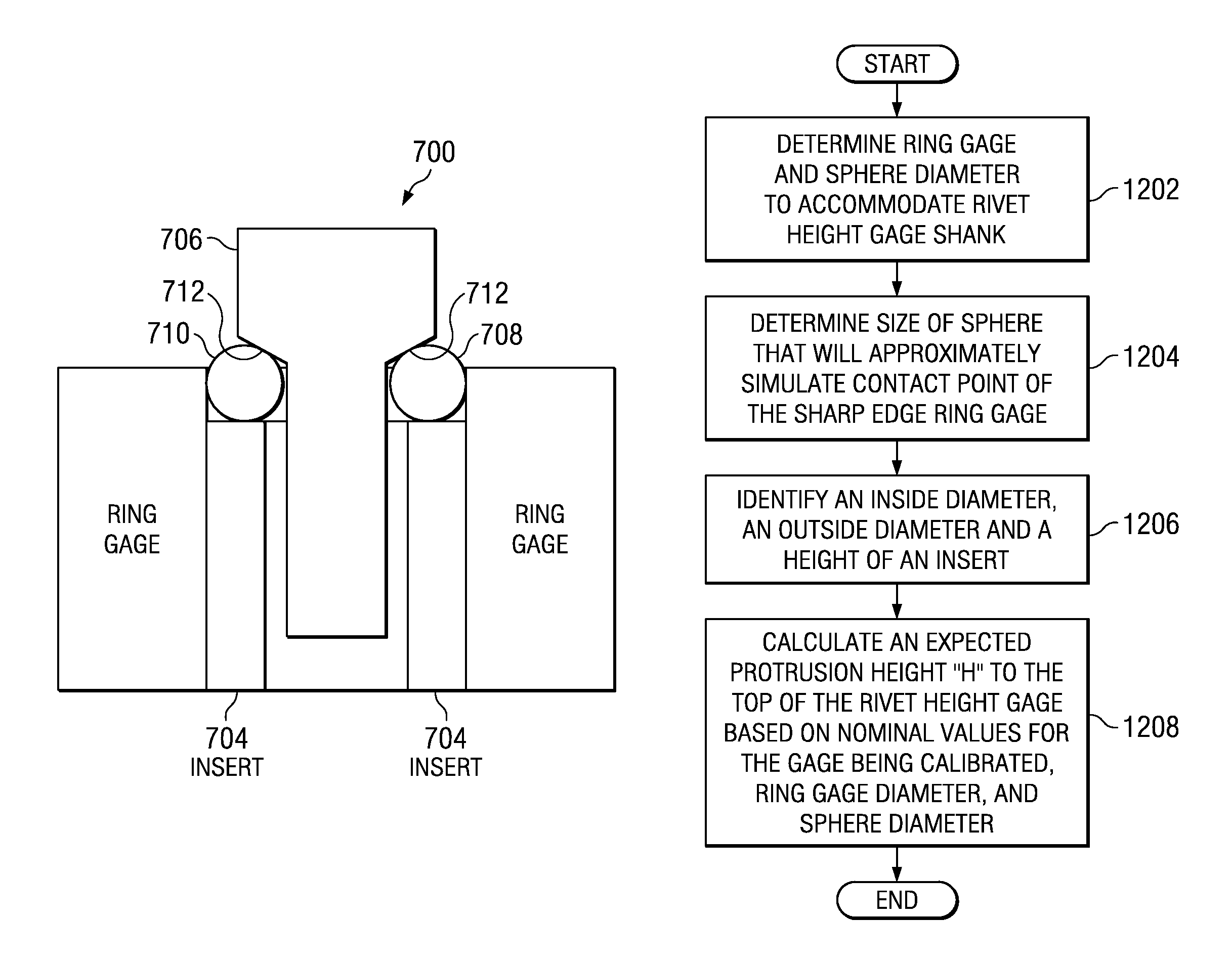
A method, apparatus, and computer usable program product for calibrating rivet height gages. In one embodiment, the process calculates a size of sphere required to create a sphere-based ring gage to simulate a contact point between a rivet height gage and a sharp edge of a specified sharp-edged ring gage. The process identifies an expected protrusion height from a top of the rivet height gage to a reference surface formed by tops of a set of spheres of the size of sphere required to simulate the contact point.

Description

BACKGROUND INFORMATION[0001]1. Field[0002]The present disclosure is related generally to a data processing system and in particular to a method and apparatus for rivet height gages. More particularly, the present disclosure is directed to a computer implemented method, apparatus, and computer usable program code for calibrating rivet height gages.[0003]2. Background[0004]Fasteners on commercial and military aircraft carry loads from one component of the aircraft to the next. A rivet is a commonly used mechanical fastener. At installation, a rivet is placed in a pre-drilled hole that may or may not be countersunk. The size and angle of the countersink should correspond to a particular countersunk rivet.[0005]A countersunk rivet is a rivet having a conical shaped head with a substantially flat outer face and tapering inner face allowing the countersunk rivet to engage the countersink in the material. Typically, the installed outer face of the rivet sits substantially flush with the su...

Claims


Application Information

Patent Timeline
Patent Type & Authority Patents(United States)
IPC IPC(8): G01B5/18G01B11/22G01B13/14G01B21/18G01B7/26
CPCG01B21/042
Inventor ASHFORD, CURTIS M.BOST, ROBERT A.KLUNK, WILLIAM J.
Owner THE BOEING CO
Why Eureka
Try Eureka