
Mobile mark removal system

a mobile mark and removal system technology, applied in the direction of cleaning using liquids, transportation and packaging, chemistry apparatus and processes, etc., can solve the problems of equipment gumminess, undesirable grooves on pavement surfaces, equipment removal, etc., to increase water flow capacity, increase horsepower, and high surface marking removal rate

Active Publication Date: 2010-09-21
WATERBLASTING
View PDF26 Cites 14 Cited by
  • Summary
  • Abstract
  • Description
  • Claims
  • Application Information

AI Technical Summary

Benefits of technology

[0016]It is yet another objective of the instant invention to provide a surface marking removal system which permits higher than standard flow rates without the additional weight of a larger engine to power the high pressure water pump.
[0017]It is still another objective of the instant invention to provide a surface marking removal system which provides increased horsepower to a high pressure pump to permit high surface marking removal rates due to increased water flow capacity.
[0018]Still yet another objective of the instant invention is to provide a surface marking removal system in which the construction of the system permits the transport of additional water without increasing weight over prior art constructions for longer operation times at typical flow rates.

Problems solved by technology

When polymers such as paint or plastic are used for roadway marking, the surface of the pavement is penetrated from ⅛-⅜ inch, so that mere surface removal of the marking material is not sufficient to remove the marking.
However, the use of these devices often results in undesirable grooves in the pavement surface.
While this type of device is effective for removal of markings, it often creates excessive heat which may melt thermoplastic materials causing equipment to gum up.
Unfortunately, these devices must remove a portion of the pavement material to effectively remove the marking, thereby leaving unsightly and potentially dangerous grooves in the pavement.
A common problem associated with these prior art devices relates to the requirement of multiple prime movers, e.g. internal combustion engines, for operation of the various systems necessary for effective stripe removal.
Internal combustion engines are generally heavy and therefore consume a substantial amount of the allowed overall weight of the vehicle.
In addition, engines consume a large amount of the bed space available on the truck.
System maintenance and fuel costs are also substantially increased with the requirement of multiple engines.
Still yet, mounting multiple engines on a single vehicle frame causes problems with proper weight distribution among the truck's various axles.

Method used


Image

  • Mobile mark removal system
  • Mobile mark removal system
  • Mobile mark removal system

Examples


Embodiment Construction

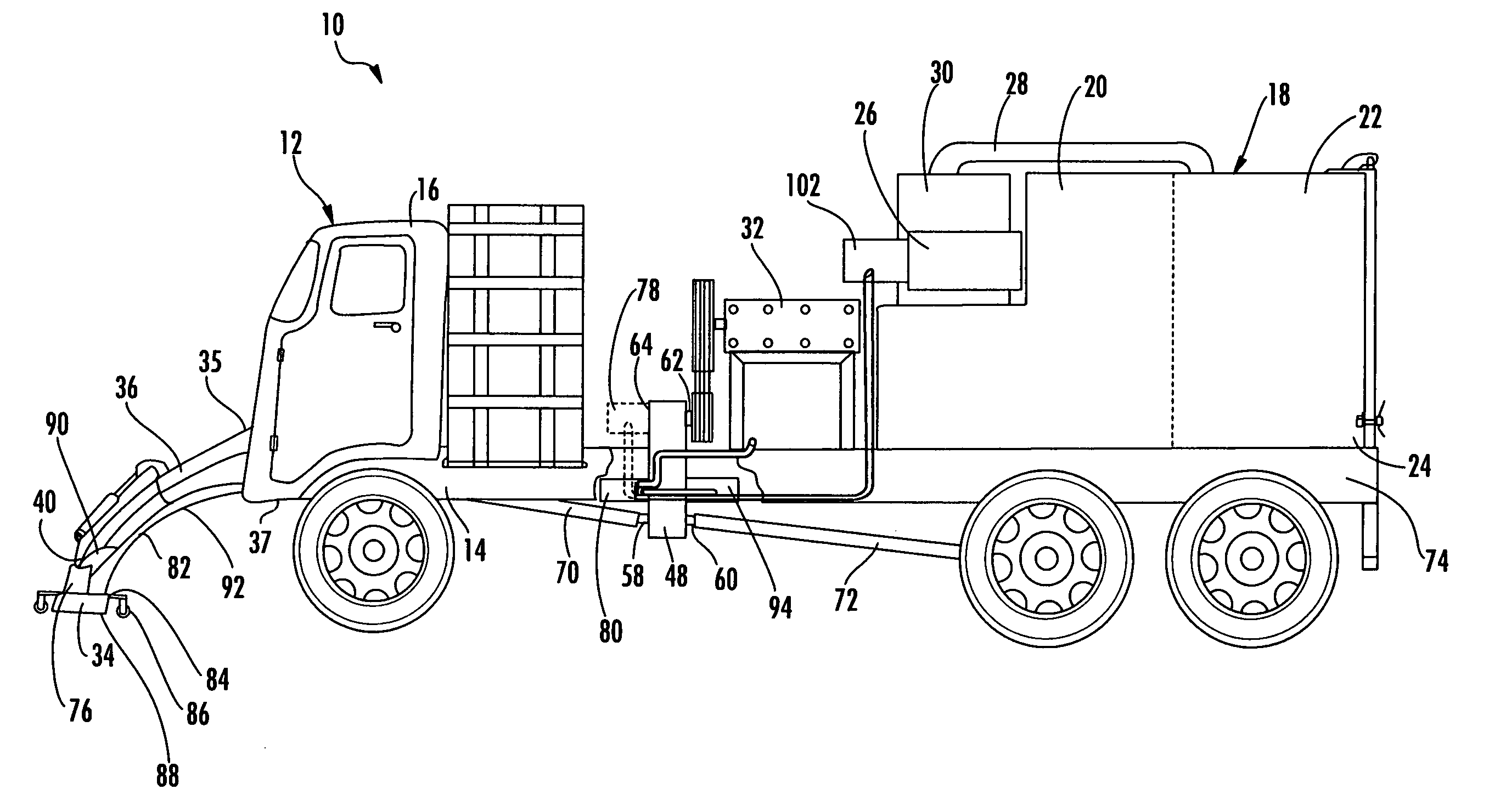
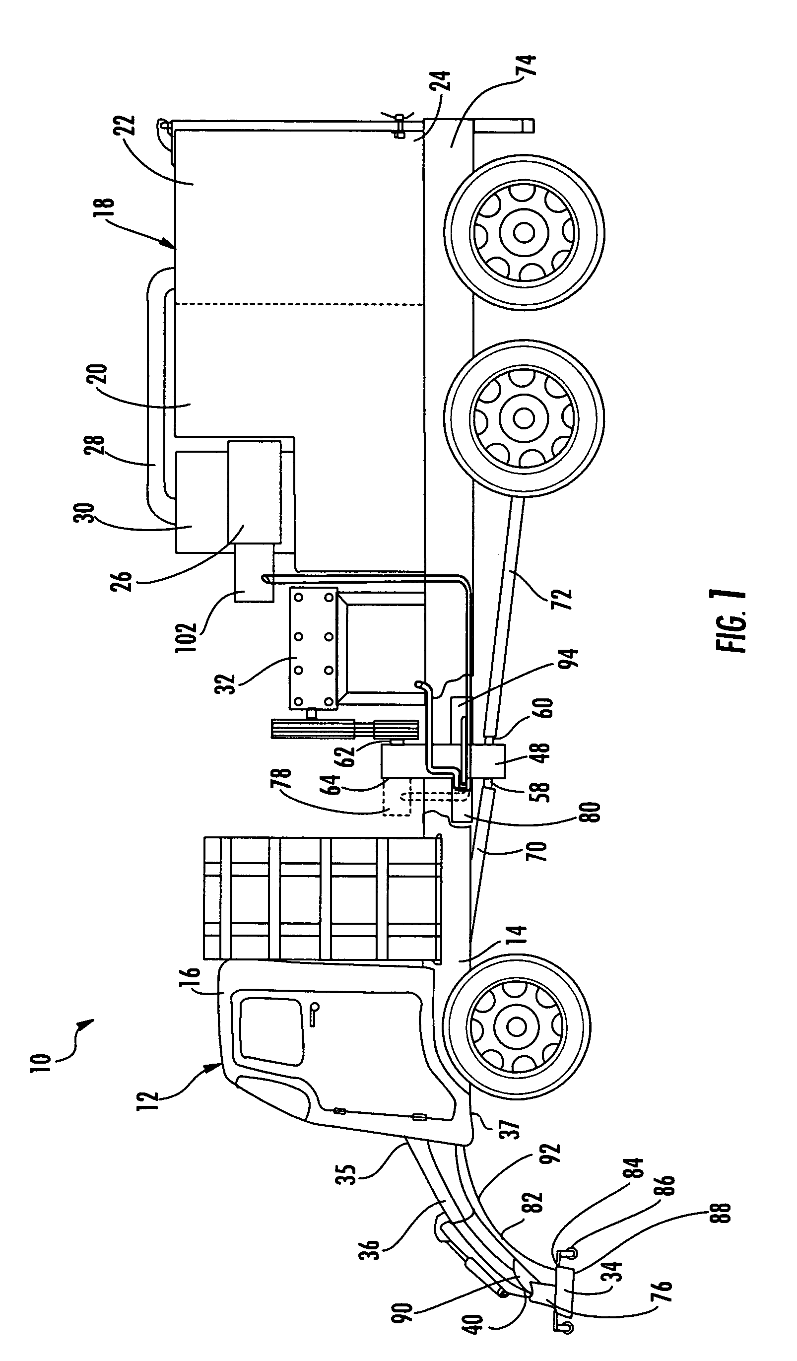
[0026]The marking removal system 10, shown in FIG. 1, includes a prime-mover truck 12 having an elongated frame 14. Mounted on a front portion of the elongated frame 14 is a cab 16 for enclosing the operator as well as the driving and operating controls. Mounted on a front portion of the frame is a prime mover 44 (FIG. 2). The prime mover is generally an internal combustion engine of a type well known in the art, utilizing diesel, gasoline, propane, natural gas or other suitable fuel.

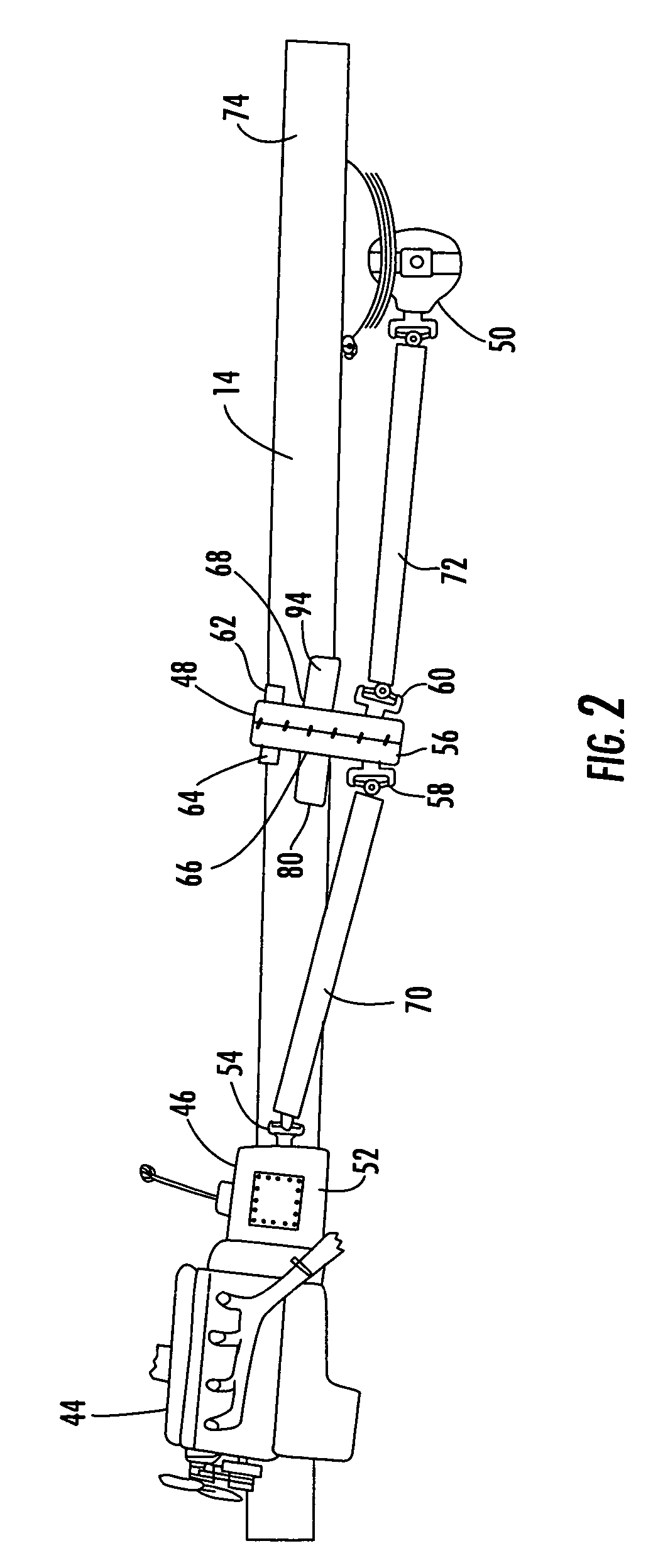
[0027]Referring to FIG. 2, the prime mover 44 is connected to the truck drive-line which includes a first transmission 46 and a second transmission 48 as well as the drive axle gears 50. The first transmission is operatively coupled to the prime mover as is well known in the art. The first transmission is preferably a manual type transmission with multiple forward and reverse gears such as is well known in the art. Alternatively, an automatic transmission having at least one forward and one reverse gear...


PUM


Abstract

Disclosed is a cleaning system for removing coatings from a hard surface by high pressure liquid. The system employs a combination liquid and vacuum reservoir connected to a high pressure pump for directing ultra high pressure water through a blast head mounted on a front portion of the vehicle. The cleaning system is preferably mounted on a single truck with a single prime mover. The drive-line of the vehicle is constructed and arranged to operate in two distinct modes, e.g. a transport mode and a work mode. In the transport mode, a first transmission coupled to the rear portion of the prime mover delivers torque from the engine to the rear wheels of the vehicle. In the work mode, the prime mover is utilized to mechanically drive the bed mounted equipment as well as provide motive force in the form of mechanical-hydrostatic transmission to propel the system at a speed suitable for marking removal.

Description

RELATED APPLICATIONS[0001]This application is related to U.S. patent application Ser. No. 10 / 884,643, filed Jul. 2, 2004 and entitled “Stripe Removal System”, now U.S. Pat. No. 7,255,116; U.S. patent application Ser. No. 11 / 340,738, filed Jan. 26, 2009; U.S. patent application Ser. No. 11 / 368,020, filed Mar. 3, 2006; U.S. patent application Ser. No. 11 / 368,035, filed Mar. 3, 2006; U.S. patent application Ser. No. 11 / 835,642, filed Aug. 8, 2007; U.S. patent application Ser. No. 12 / 394,806, filed Feb. 27, 2008 and U.S. patent application Ser. No. 12 / 395,302, filed Feb. 27, 2009, the contents of which are incorporated herein in their entirety.FIELD OF THE INVENTION[0002]This invention relates to the field of high pressure water cleaning devices for highways, runways, parking decks, and other hard surfaces.PRIOR ART BACKGROUND[0003]The use of paint stripes on road surfaces is the accepted method to indicate vehicle lanes, crossing lanes, parking areas and numerous other indicators. Vari...

Claims


Application Information

Patent Timeline
Patent Type & Authority Patents(United States)
IPC IPC(8): B08B3/12
CPCB08B3/024B60K17/28E01H1/103B60K17/22
Inventor CROCKER, JAMES P.
Owner WATERBLASTING
Learn More