
Variable air inflow structure of engine

An intake structure and variable technology, applied in the direction of combustion air/combustion-air treatment, engine components, machines/engines, etc., can solve the problems of not being able to meet the requirements of intake efficiency and performance at the same time

Inactive Publication Date: 2011-06-15
KYMCO
View PDF4 Cites 5 Cited by
  • Summary
  • Abstract
  • Description
  • Claims
  • Application Information

AI Technical Summary

Problems solved by technology

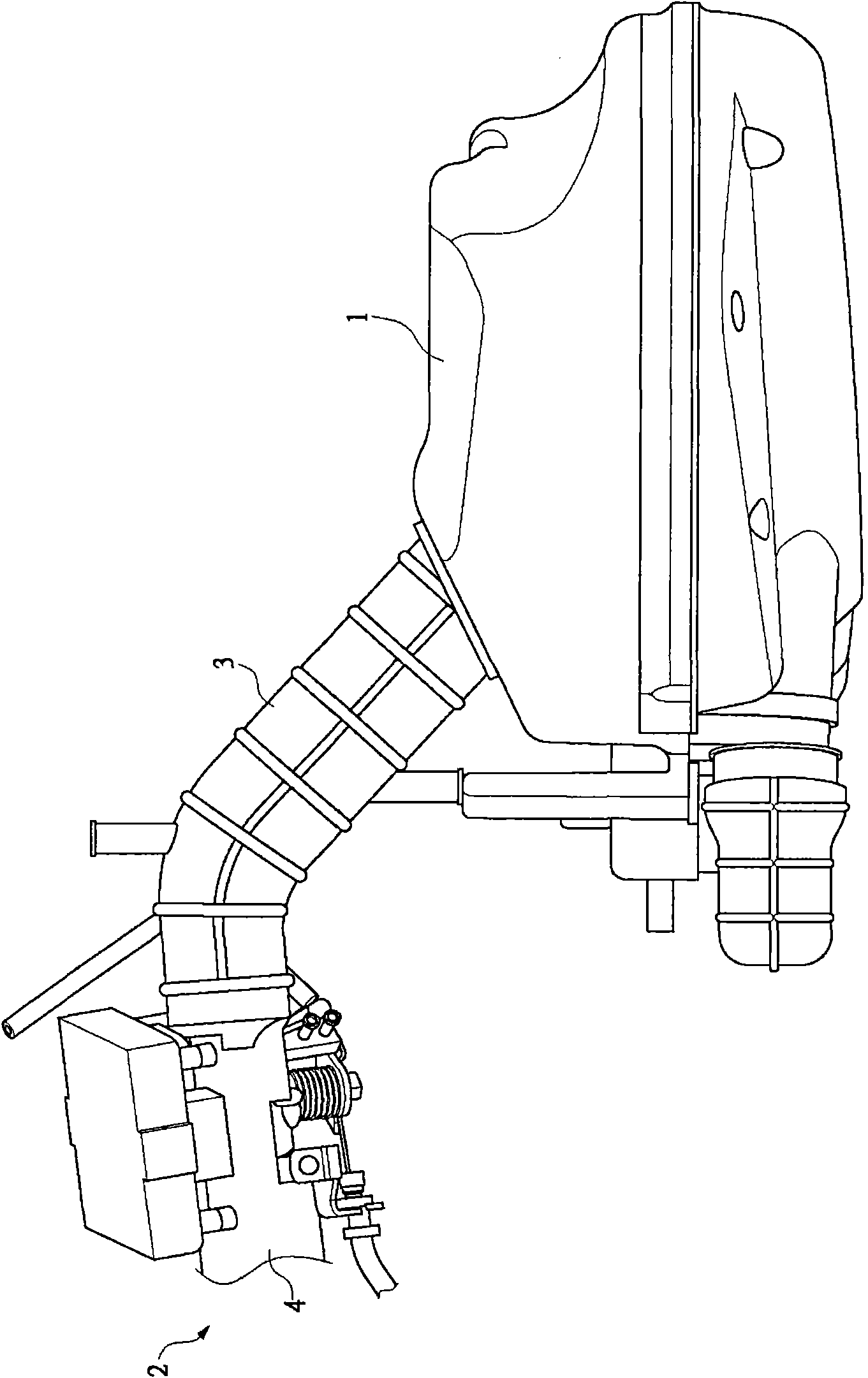
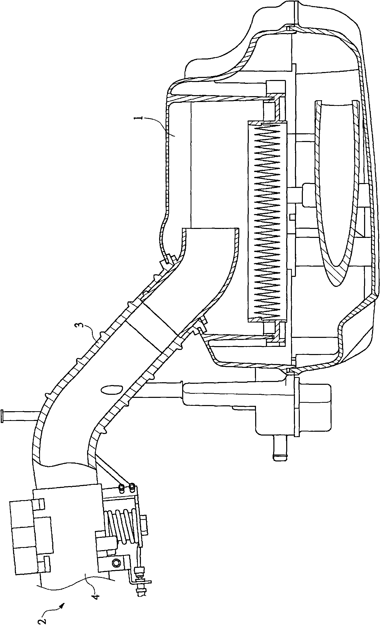
[0003] However, for the design of the air intake pipeline of the general scooter motorcycle engine at present, please refer to figure 1 , 2 As shown, it is mainly to arrange an intake manifold 3 between the air filter 1 of the motorcycle and the intake variable member 2 (which can be a carburetor or a throttle body), and the intake manifold 3 The front end is provided with a throttle valve body 4, because the cross-sectional area and length of the intake manifold 3 are all fixed, when the engine runs to generate negative pressure suction, the intake manifold 3 can only meet the requirements of lower speed or higher speed. One of the air intake requirements at high speeds cannot meet the air intake efficiency requirements of the global speed, which will result in the lack of simultaneous performance of lower speeds and higher speeds

Method used


Image

  • Variable air inflow structure of engine
  • Variable air inflow structure of engine
  • Variable air inflow structure of engine

Examples


Embodiment Construction

[0035] In order to make it easier to understand the structure of the present invention and the effect that can be achieved, it is described as follows in conjunction with the drawings:

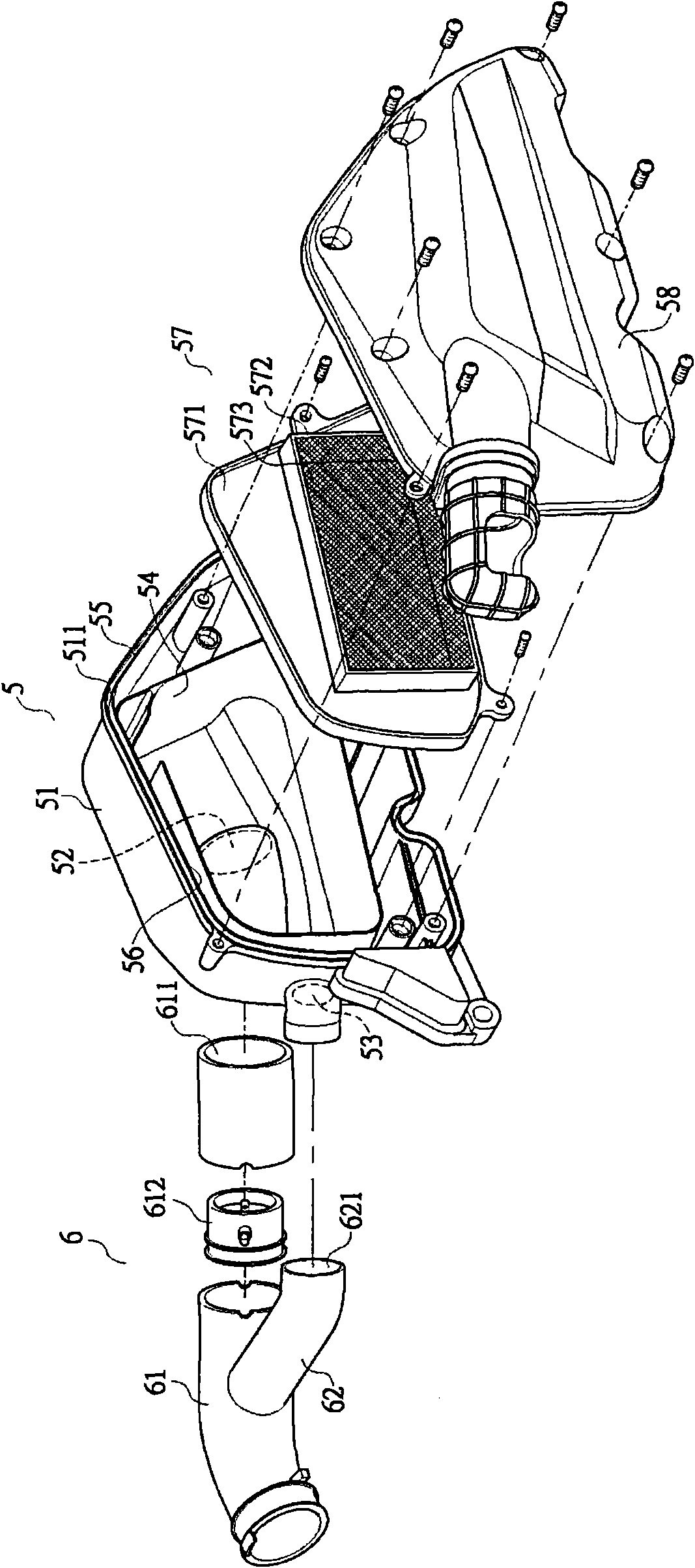
[0036] First, see image 3 , 4 As shown, the engine variable intake structure of the present invention at least includes an air filter 5, an intake manifold 6, an intake variable member (which can be a carburetor or a throttle body) 7 (hereinafter only Take the throttle body as the implementation description of this case).

[0037] The air filter 5 has a box body 51, a first air inlet 52 and a second air inlet 53 are arranged at its front end, and an intake manifold 6 is connected to the front end of the first air inlet 52, and an air intake manifold 6 is arranged at the front end of the first air inlet 52. The inside of the box body 51 is provided with a partition plate 54 that surrounds the box body 51. The partition plate 54 and the ring wall 55 of the box body 51 can just form an air pas...


PUM


Abstract

The invention discloses a variable air inflow structure of an engine. The variable air inflow structure is mainly characterized in that an air inflow manifold is arranged between an air cleaner and a variable air inflow structural member of a motorcycle; the air inflow manifold comprises a high-speed manifold and a low-speed manifold; the front end of the high-speed manifold is provided with the variable air inflow structural member, and the other end of the high-speed manifold is connected with the air cleaner through a first inlet, wherein the high-speed manifold is provided with a rotary valve; the low-speed manifold is arranged between the rotary valve of the high-speed manifold and the variable air inflow structural member in an extending manner; the other end of the low-speed manifold is connected with the air cleaner through a second inlet, and forms an air duct with an annular wall by means of a baffle plate in the air cleaner; and the flow duct of the low-speed manifold can be prolonged in a limited space, so that the performance of high and low speed of the engine is considered simultaneously, and the efficacy of miniaturization of the low-speed manifold can be achieved.

Description

【Technical field】 [0001] The invention relates to a variable air intake structure of an engine, in particular to a cylinder head structure of a water-cooled engine that can improve the heat dissipation of the cylinder head and enhance the anti-knock strength of the cylinder head. 【Background technique】 [0002] In the engine design of a general scooter motorcycle, the design of the intake pipeline and the mutual cooperation between the engine are extremely important. For example, when the engine is at a slow or low speed, the required cross-sectional area of ​​the intake pipeline is relatively small Small size and long length can help to increase the gas flow velocity in the intake pipe, and thus enhance the inertial effect and pulsation effect, thereby improving the intake efficiency and increasing the engine torque; on the contrary, when the engine is running at a fast or high speed, its The required cross-sectional area of ​​the intake pipe is relatively large and the len...

Claims


Application Information

Patent Timeline
Patent Type & Authority Applications(China)
IPC IPC(8): F02M35/104
Inventor 陈昭安何昭昌
Owner KYMCO
Learn More