Muffler and/or exhaust apparatus and method of manufacture

a technology of exhaust apparatus and exhaust pipe, which is applied in the field of mufflers, can solve the problems of less advantageous, and achieve the effects of reducing the diameter of the first end, and uniform starting diameter

Inactive Publication Date: 2017-11-02
TORQUE RES & DEV INC
View PDF3 Cites 5 Cited by
  • Summary
  • Abstract
  • Description
  • Claims
  • Application Information

AI Technical Summary

Benefits of technology

[0010]In at least one of these improved manufacturing embodiments, a perforated or “louvered” gas flow core (e.g., hollow cylinder) is encapsulated within an outer muffler shell utilizing metal forming (preferably swaging) techniques. Such a core includes louvers or specially configured perforations, in certain embodiments, to intercept sound waves generated by an operating engine at crimps, indentations, or curves, and / or permits such sound waves to travel through provided perforations, to reflect, deflect, slow, and / or cancel sound waves to change engine and / or muffler acoustical characteristics. In certain embodiments, the spacing, size, orientation, and configuration of such perforations or louvers is tailored such that the muffler simultaneously acts to improve engine performance while also “tuning” the acoustical characteristic of the vehicle (e.g., motorcycle) on which it is installed.
[0011]In certain preferred example (non-limiting) embodiments, improved muffler configurations (e.g., for motorcycles) are provided in which exhaust gas throughput velocity is increased or other flow characteristics are improved. In such example embodiments, decibel suppression functionality is maintained while simultaneously providing engine performance improvements. Such engine performance improvements include, but are not limited to, increased horsepower and / or increased fuel efficiency.
[0013]In at least one particularly useful embodiment of the invention, there is provided: a method of making a muffler for an engine comprising: providing a hollow cylinder comprised of a formable material having an interior muffler volume, to serve as a muffler shell, the hollow cylinder having a starting diameter and having first and second ends, the first end including an inlet opening and the second end including an outlet opening; performing a first forming operation on the first end of the hollow cylinder to reduce the diameter of the first end, the first forming operation also imparting a first taper to the first end of the hollow cylinder; providing a hollow gas flow tube having an inflow end and an outflow end and having a plurality of apertures located and spaced apart on wall portions thereof, and locating the hollow gas flow tube inside of the interior muffler volume; performing a second forming operation on the second end of the hollow cylinder to enclose the hollow gas flow tube inside of the interior muffler volume and to reduce the diameter of the outlet opening of the second end to approximately match the diameter of the outflow end of the hollow gas flow tube, the second forming operation also imparting a second taper to the second end of the hollow cylinder; and performing a sealing operation to eliminate annular gas flow gaps between the outflow end of the hollow gas flow tube and the outlet opening of the second end of the hollow cylinder.
[0014]In another useful embodiment of the invention, there is provided a method of making a muffler for a motorcycle engine comprising: providing a hollow metal cylinder having an interior muffler volume, to serve as a muffler shell, the hollow metal cylinder having a substantially uniform starting diameter and having first and second ends, the first end including an inlet opening and the second end including an outlet opening; performing a first swaging operation on the first end of the hollow metal cylinder to reduce the diameter of the first end, the first swaging operation also imparting a first taper to the first end of the hollow metal cylinder; performing a second swaging operation on the second end of the hollow metal cylinder to reduce the diameter of the second end, the second swaging operation also imparting a second taper to the second end of the hollow metal cylinder, the second taper being angularly oriented at a reverse angle relative to the first taper; providing a hollow metal gas flow tube having an inflow end and an outflow end and having a plurality of apertures located and spaced apart on wall portions thereof, and locating the hollow metal gas flow tube inside of the interior muffler volume; performing a third swaging operation on the second end of the hollow metal cylinder to enclose the hollow metal gas flow tube inside of the interior muffler volume and to reduce the diameter of the outlet opening of the second end to approximately match the diameter of the outflow end of the hollow metal gas flow tube; and performing a sealing operation to eliminate annular gas flow gaps between the outflow end of the hollow metal gas flow tube and the outlet opening of the second end of the hollow metal cylinder.
[0021]Although the methods described herein eliminate many difficult welding operations such as when fabricating an outer muffler shell from rolled sheet steel (which requires a full muffler length weld), welds may be employed with the herein described invention without departing from the scope thereof. For example, in the sealing step where the annular spaces between the outflow end of the central core and the outlet end of the outer shell are closed or sealed, it is sometimes desirable to obtain such “seals” using TIG welds. Moreover, in certain embodiments, prior to such sealing, an end cutting operation may be performed to even the edges of the core and shell outflow / outlet ends (e.g., so that they may be more easily welded together).

Problems solved by technology

Although, in preferred embodiments, the metal forming techniques include swaging operations, other metal forming techniques may be employed though they may be less advantageous as being less cost effective (or the may require more skill), for example.

Method used


Image

  • Muffler and/or exhaust apparatus and method of manufacture
  • Muffler and/or exhaust apparatus and method of manufacture
  • Muffler and/or exhaust apparatus and method of manufacture

Examples


Embodiment Construction

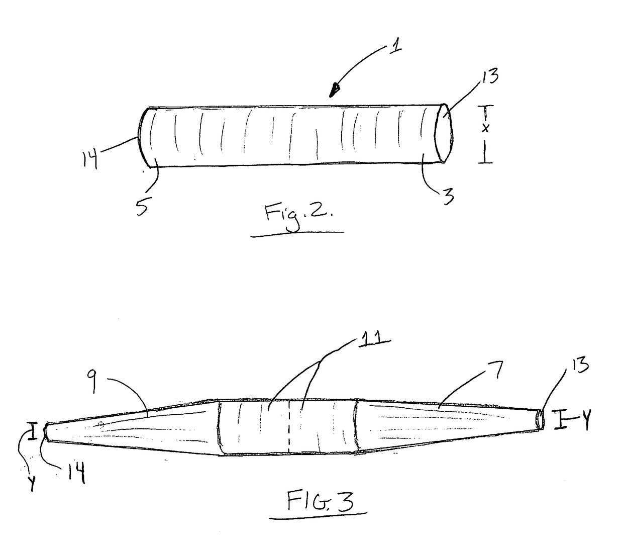
[0038]For a more complete understanding of the present invention, reference is now made to the following description of various illustrative and non-limiting embodiments thereof, taken in conjunction with the accompanying drawings in which like reference numbers indicate like features.

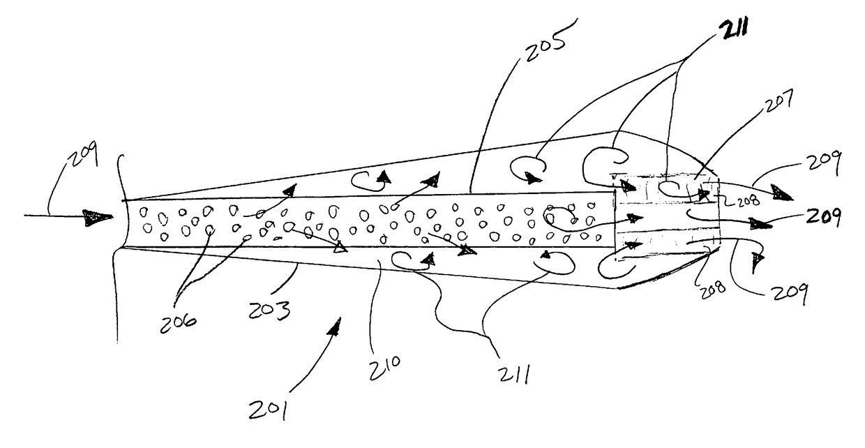
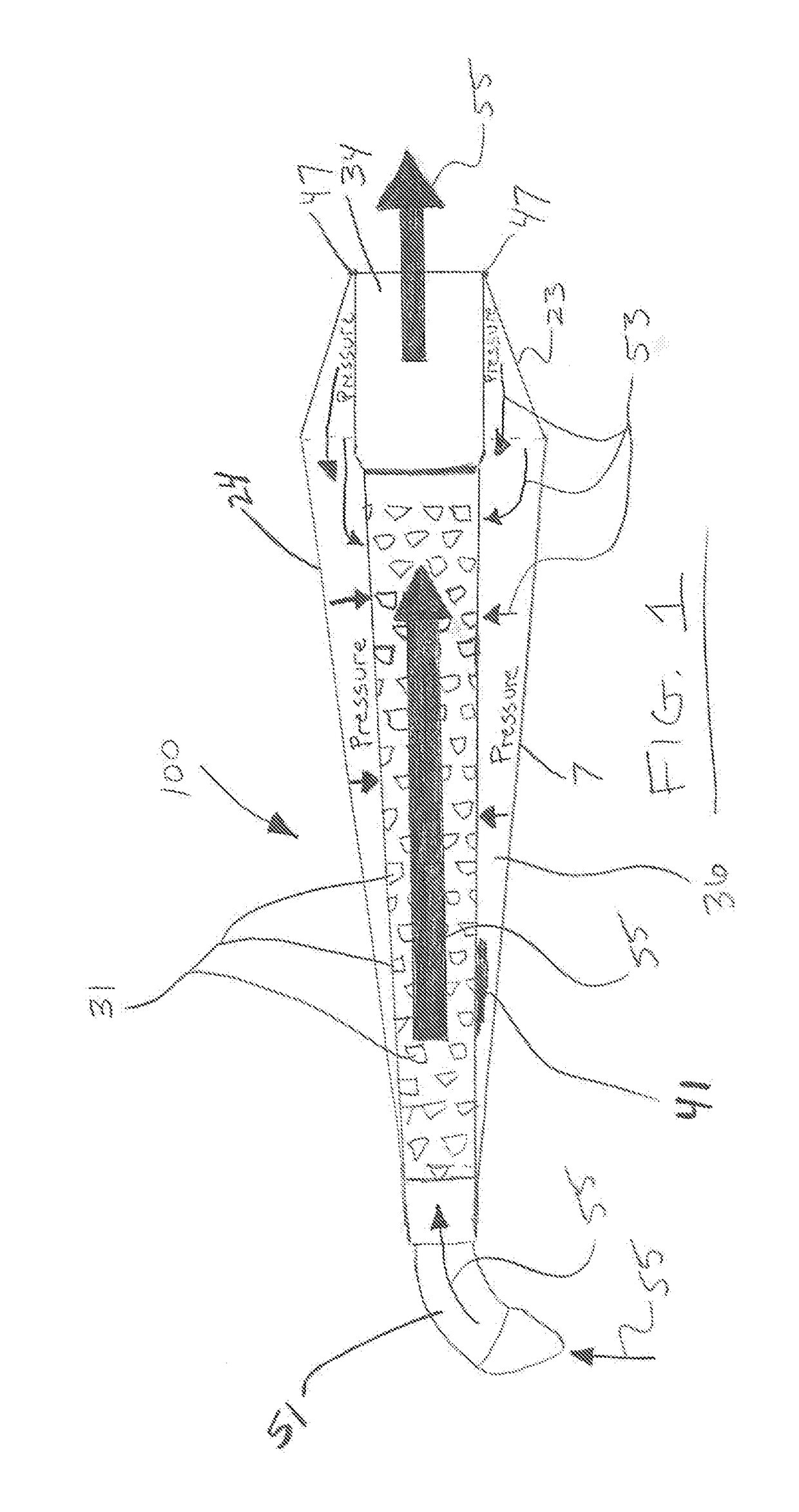
[0039]In preferred embodiments of this invention, a manufacturing process is provided which results in improved manufacturing yields and / or reduced manufacturing and / or labor costs. In these same preferred embodiments, a superior muffler, such as the muffler 100 illustrated in FIG. 1, is obtained from the manufacturing process in which structural integrity is increased with the muffler also providing increased engine performance and / or efficiency by delivering a higher cubic-feet-per-minute exhaust gas output (e.g., higher exhaust gas output velocity). In certain installations, this improved exhaustion of combustion gas reduces heat in the headers and increases engine horsepower, while also providing a...


PUM

PropertyMeasurementUnit
diameteraaaaaaaaaa
diameteraaaaaaaaaa
volumeaaaaaaaaaa

Abstract

Mufflers with unique configurations which, in certain (but not all) embodiments, improve engine performance. In other embodiments, improved manufacturing processes and methods for making mufflers. In particularly preferred embodiments, methods for making motorcycle mufflers with swaging techniques. In still other preferred embodiments, swaged motorcycle mufflers with improved exhaust flow. In still other embodiments, aftermarket mufflers which can be assembled to a variety of engine exhaust systems utilizing a universal coupler.

Description

RELATED APPLICATION DATA[0001]None.FIELD OF THE INVENTION[0002]This invention relates to mufflers with unique configurations which, in certain (but not all) embodiments, improve engine performance. In other embodiments, the invention relates to improved manufacturing processes and methods for making mufflers. In particularly preferred embodiments, the invention relates to methods for making motorcycle mufflers with swaging techniques. In still other preferred embodiments, the invention relates to swaged motorcycle mufflers with improved exhaust flow. In still other embodiments, the invention relates to aftermarket mufflers which can be assembled to a variety of engine exhaust systems utilizing a universal coupler.BACKGROUND OF THE INVENTION[0003]Mufflers, as components of exhaust systems, are well known in the art as used on automobiles and motorcycles. Indeed, due to noise laws and ordinances at both the federal and local level, mufflers are typically required by law to limit exhib...

Claims


Application Information

Patent Timeline
Patent Type & Authority Applications(United States)
IPC IPC(8): F01N1/08B23P15/00
CPCB23P15/00F01N1/083B21D41/04B21D53/84F01N1/08F01N2470/02F01N2490/16F01N2590/00F01N2590/04
Inventor PANTHER, JASON B.PANTHER, JAMES B.BLEVINS, RANDY
Owner TORQUE RES & DEV INC
Why Eureka
Try Eureka