High vacuum valve

a high-pressure valve and valve body technology, applied in the direction of valve details, valve arrangement, spindle sealing, etc., can solve the problems of poor flexibility and bending properties of molded bellows, the possibility of reducing the life of the product, and poor bending properties, so as to reduce the manufacturing cost of the valve, reduce the length of the bellows, and improve the durability.

Active Publication Date: 2010-09-21
SMC CORP
View PDF11 Cites 5 Cited by
  • Summary
  • Abstract
  • Description
  • Claims
  • Application Information

AI Technical Summary

Benefits of technology

[0010]It is therefore an object of the present invention to provide a high vacuum valve which is superior in durability in that it can withstand the application of the valve under severe conditions that the valve is subjected to repeated application of high fluid-pressure, and which is inexpensive in that the manufacturing cost of the valve can be restricted.
[0013]According to the present invention, both the tubular member and the welded bellows superior to a molded bellows in flexibility are employed in order to hermetically surround the periphery of the valve shaft, thereby making it possible to restrict a length of the bellows while ensuring a flexing amount of the bellows which is required in connection with a stroke amount of the valve shaft. Consequently, it is possible to attain a reduction in the manufacturing cost of the valve.
[0014]Moreover, the welded bellows which is superior to the molded bellows in bending property is employed and the length of the welded bellows can be restricted to be short as discussed above, so that according to the present invention, there is provided the high vacuum valve which is superior in durability in that it can withstand the application of the valve under severe conditions that the valve is subjected to repeated application of high fluid-pressure, and in which a long life of the valve is ensured.

Problems solved by technology

However, on the other hand, the molded bellows is poor in flexibility and bending property.
When such a force in the bending direction is repeatedly applied to the metal bellows, crack or the like is easy to be produced in the bellows by metal fatigue which is brought about by repeated bent-deformation of the bellows, so that there is a possibility that a life of the product will be reduced.
This is noticeable particularly in the case of the molded bellows having the poor bending property as discussed above.
However, in the conventional high vacuum valve, if the length of the metal bellows is reduced in preference to durability, a sufficient stroke amount of the valve shaft, namely, a sufficient increase in valve-member opening can not be ensured, since the molded bellows is poor in flexibility as discussed above.
Consequently, there is a problem that a sufficient flow rate of fluid allowed to flow by the valve can not be ensured.

Method used


Image

  • High vacuum valve
  • High vacuum valve
  • High vacuum valve

Examples


Embodiment Construction

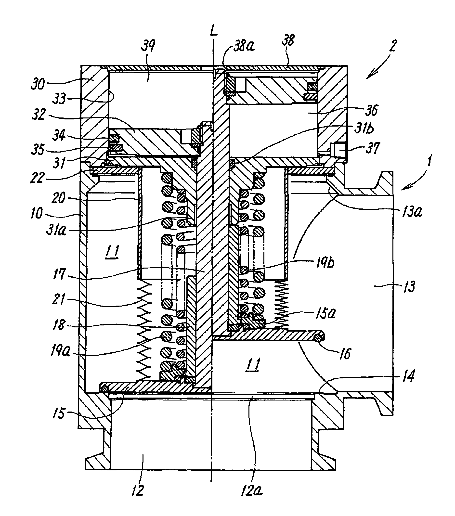
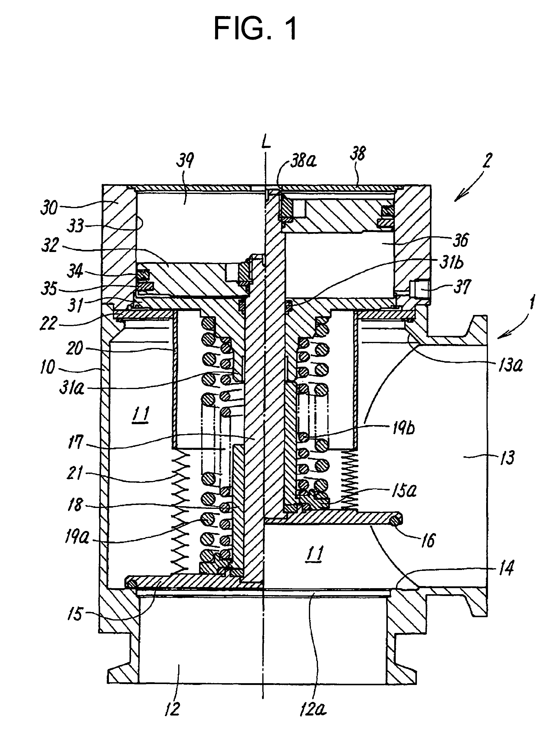
[0017]Referring to FIG. 1, there is illustrated a high vacuum valve according to a first embodiment of the present invention. The valve comprises a valve body section 1, in which a valve flow channel 11 for causing a first port 12 and a second port 13 to be communicated with each other is adapted to be opened and closed by a valve member 15, and a fluid-pressure valve member driving section 2 which includes a piston 32 for causing the valve member 15 to perform opening / closing operations.

[0018]The valve body section 1 comprises a valve housing 10 which is formed into a substantially cylindrical-shape or a substantially square pole-shape and has first and second ends in a direction of an axial line L. The valve housing 10 comprises the valve flow channel 11 of a substantially circular shape in cross-section extending in the direction of the axial line L in the interior of the valve housing 10, the first port 12 provided on the side of the first end of the valve housing 10 so as to be...


PUM


Abstract

The high vacuum valve includes a valve housing having a valve flow channel provided in an interior thereof, two ports connected to the valve housing so as to be arranged perpendicular relative to each other, and capable of being communicated with each other through the valve flow channel, a valve member housed in the valve flow channel for opening and closing the valve flow channel, a valve shaft received in the valve flow channel for causing the valve member to perform opening / closing operations, and an assembly comprising a tubular member and a welded bellows and hermetically surrounding a periphery of the valve shaft, the assembly being fixed at one end portion thereof to a rear face of the valve member and fixed at the other end portion thereof to a portion of the interior of the valve housing which is opposed to the rear face of the valve member.

Description

CROSS-REFERENCES TO RELATED APPLICATIONS[0001]The present application is related to the Japanese Patent Application No. 2007-008197, filed Jan. 17, 2007, the entire disclosure of which is expressly incorporated by reference herein.BACKGROUND OF THE INVENTION[0002]1. Field of the Invention[0003]The present invention relates to a high vacuum valve which is to be used in order to depressurize a vacuum chamber for chemical reaction in a physical or chemical machine or the like, and which is to be used in other fields.[0004]2. Description of the Related Art[0005]For example, in a manufacturing apparatus for producing a semiconductor, a chemical treatment such as etching is performed in a vacuum chamber. At this time, a vacuum pump is used in order to depressurize the vacuum chamber and a high vacuum valve is used for closing and opening an external flow-channel which interconnects the vacuum pump and the vacuum chamber.[0006]As shown, for example, in FIG. 2, the high vacuum valve general...

Claims


Application Information

Patent Timeline
Patent Type & Authority Patents(United States)
IPC IPC(8): F16K31/00
CPCF16K31/122F16K41/10F16K51/02
Inventor SAKURAI, TOYONOBU
Owner SMC CORP
Why Eureka
Try Eureka