Bone fusion device and methods

a bone fusion and bone technology, applied in the field of bone fusion devices, systems, kits, methods, etc., can solve the problems of requiring an undetectable incision, reducing stability, temporary or permanent nerve damage, etc., and reducing the effect of stability

Active Publication Date: 2010-09-21
KYPHON
View PDF53 Cites 73 Cited by
  • Summary
  • Abstract
  • Description
  • Claims
  • Application Information

AI Technical Summary

Benefits of technology

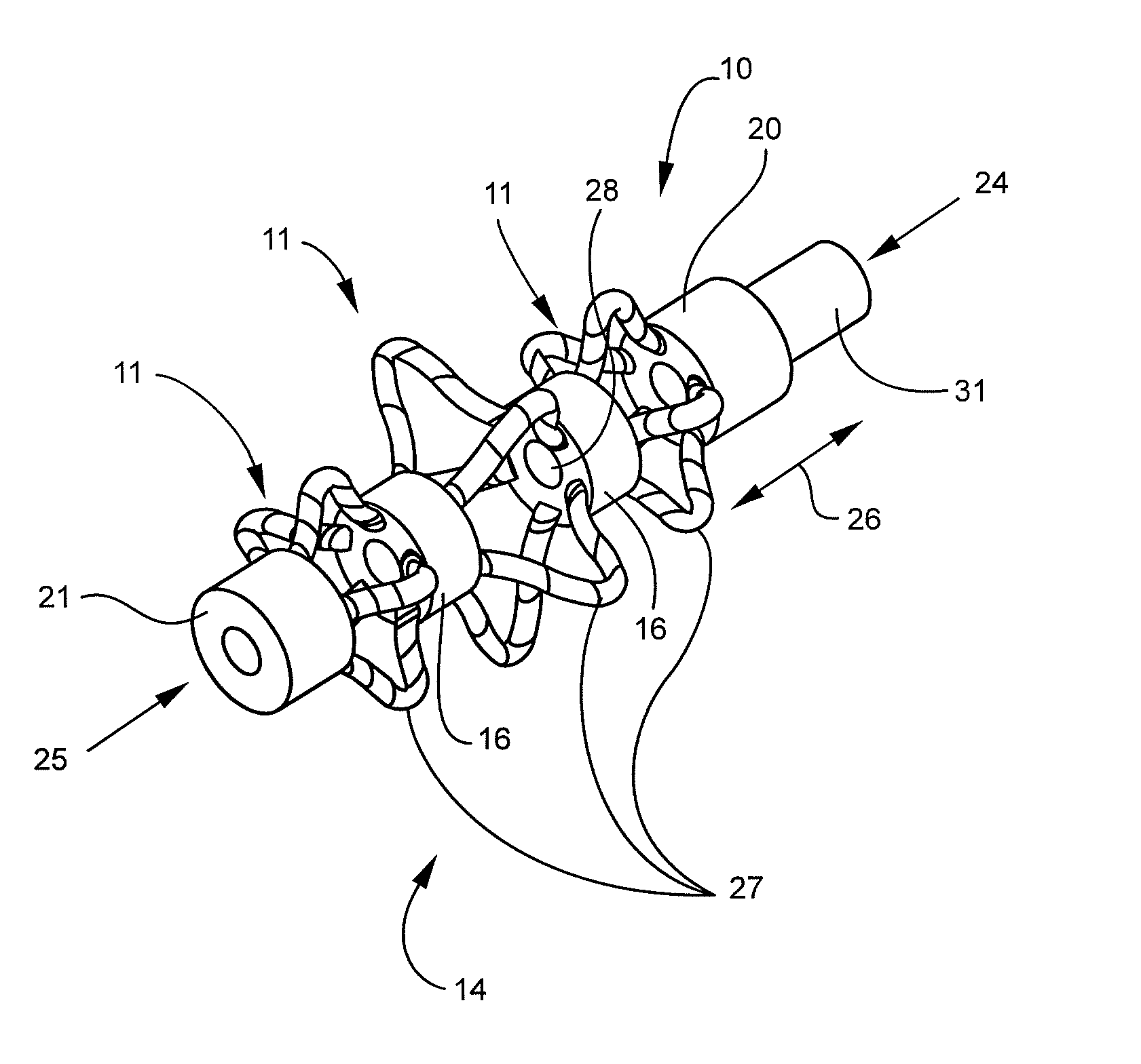
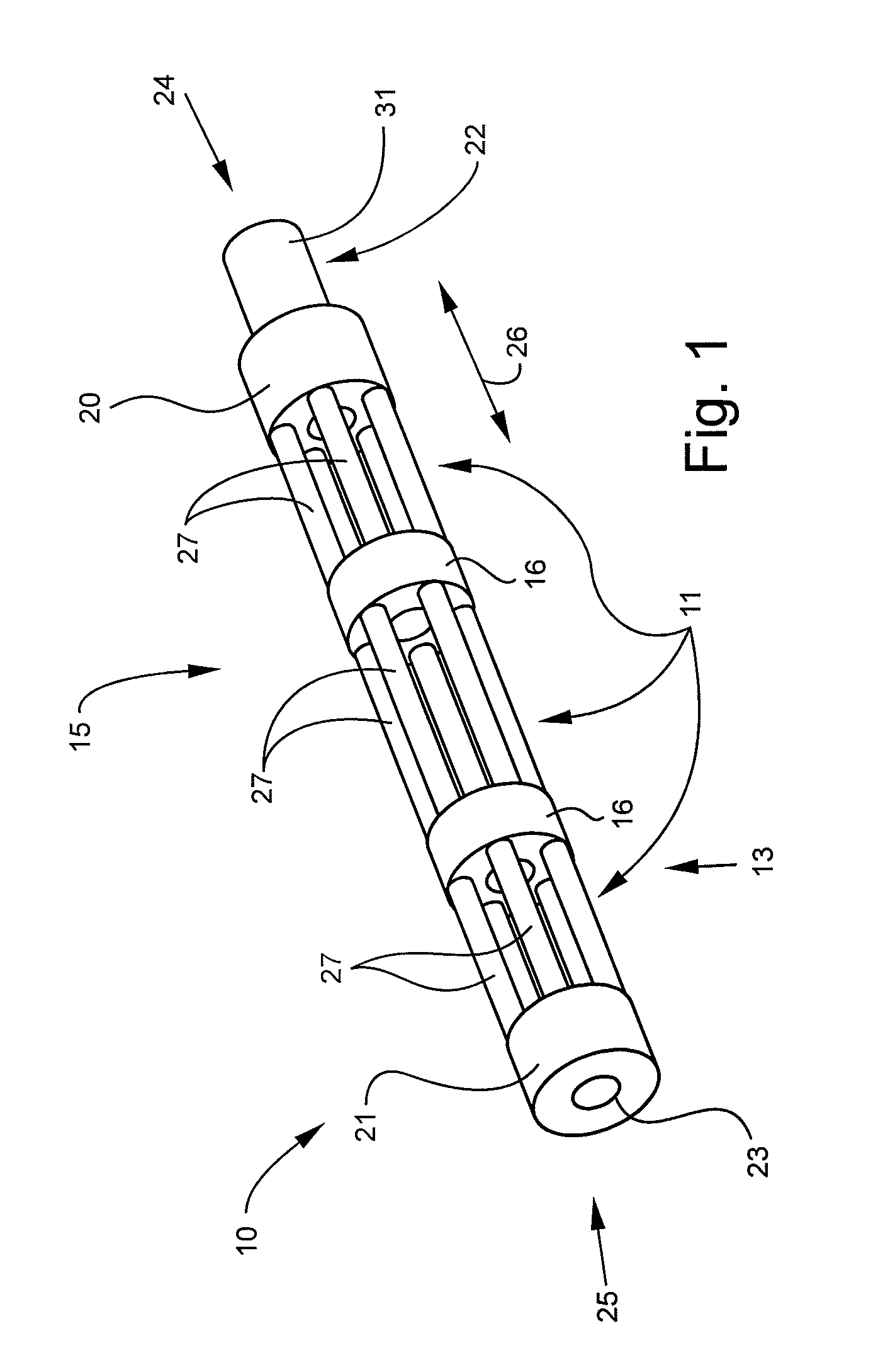
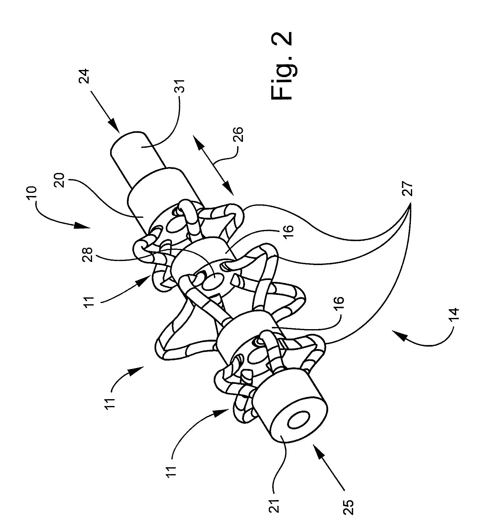
[0011]In some embodiments, one end of the at least one deformable segment can be connected to a proximal anchor portion at a proximal end of the elongated structure, and another end of the at least one deformable segment can be connected to a distal anchor portion at a distal end of the elongated structure. An internal rod can extend through the elongated structure along the longitudinal axis and be detachably attached to the distal anchor. A pushing tube slidable about the internal rod and can be detachably attached to the proximal anchor portion. Translation of the pushing tube and the proximal anchor portion along the inner rod toward a fixed position of the distal anchor portion can compress the deformable members so as to deform each deformable segment to the expanded configuration.

Problems solved by technology

Although larger heights may be clinically indicated, wider implants are generally not desirable since increased width requires removal of more bone for access to the intervertebral space, which can lead to decreased stability, and more retraction of nerve roots, which can lead to temporary or permanent nerve damage.
These devices have disadvantages.
For example, the support plates may require expansion prior to insertion, or the plates may be operatively connected by externally disposed linkage mechanisms, either of which can cause the device to have dimensions requiring an undesirably large incision for (minimally invasive) delivery to an intervertebral space.
Other devices may be expandable after being inserted, but can be difficult to operate in a restricted space such as a collapsed intervertebral space.
Conventional bone fusion devices can involve other difficulties or be associated with other less desirable results.
For example, some conventional fusion devices are designed to be impacted into the intervertebral space, which can lead to difficulty in placing the device in a desired position, and can unnecessarily traumatize the vertebral bodies or surrounding nerve and / or vascular tissue.
Some of the interbody fusion devices rely on gravity alone to stabilize the device between vertebrae, which can lead to undesirable motion between the vertebrae and difficulty in achieving a complete fusion, at least without the aid of some additional stabilizing device, such as a rod or plate.
Moreover, some of the devices are not structurally strong enough to support the heavy loads and bending forces at certain levels of the spine, in particular, the lumbar spine.
Since bone growth is enhanced by stressing or loading the bone material, such “stress-shielding” can greatly increase the time for complete bone growth, or disturb the quality and density of the ultimately formed fusion mass.

Method used


Image

  • Bone fusion device and methods
  • Bone fusion device and methods
  • Bone fusion device and methods

Examples


Embodiment Construction

[0024]For the purposes of this specification, unless otherwise indicated, all numbers expressing quantities, conditions, and so forth used in the specification are to be understood as being modified in all instances by the term “about.” Accordingly, unless indicated to the contrary, the numerical parameters set forth in the following specification are approximations that can vary depending upon the desired properties sought to be obtained by the present invention. At the very least, and not as an attempt to limit the application of the doctrine of equivalents to the scope of the claims, each numerical parameter should at least be construed in light of the number of reported significant digits and by applying ordinary rounding techniques.

[0025]Notwithstanding that the numerical ranges and parameters setting forth the broad scope of the invention are approximations, the numerical values set forth in the specific examples are reported as precisely as possible. Any numerical value, howe...


PUM


Abstract

A bone fusion device, system, kit, and / or method can include an elongated structure including at least two anchor portions and at least one deformable segment connected on each end to one of the at least two anchor portions. Each deformable segment can include a plurality of spaced apart deformable members deformable from an unexpanded configuration to an expanded configuration. The bone fusion device may be implanted between two bone structures in the unexpanded configuration utilizing a minimally invasive surgical procedure. The deformable members can be compressed along a longitudinal axis of the device to deform the deformable members to the expanded configuration into contact with the two bone structures. A bone growth promoting material can be placed in the anchor portion lumen and in the interior of each deformable segment to promote bone in-growth between the bone structures.

Description

FIELD OF THE INVENTION[0001]The present invention relates to bone fusion devices, systems, kits, and methods. Embodiments of the present invention can be used for fusion of joints, and may be particularly useful for fusion of intervertebral joints.BACKGROUND[0002]Spinal fusion, also known as spondylosyndesis, is a surgical procedure in which two or more vertebrae are fused together to stop the motion between them. Spinal fusion can be used to treat various pathological and / or traumatic conditions, including, for example: injury to the vertebrae; protrusion and / or degeneration of the intervertebral disc between vertebrae (“slipped” disc or herniated disc); abnormal curvatures of the spine (such as scoliosis or kyphosis); and a weak or unstable spine caused by infections or tumors. Spinal fusion can eliminate motion between vertebral segments, which can be a significant source of pain in some patients. The surgery can also stops the progress of spinal deformity, such as scoliosis.[000...

Claims


Application Information

Patent Timeline
Patent Type & Authority Patents(United States)
IPC IPC(8): A61B17/70A61F2/44
CPCA61F2/4455A61F2/446A61F2/4611A61F2002/2835A61F2002/30224A61F2002/30235A61F2002/30454A61F2002/30538A61F2002/30545A61F2002/30579A61F2002/30601A61F2002/30607A61F2002/30841A61F2002/448A61F2002/4627A61F2002/4629A61F2220/0058A61F2230/0069A61F2250/0006A61F2250/001A61F2250/0062A61F2002/30451
Inventor SANKARAN, MEERA
Owner KYPHON
Why Eureka
Try Eureka