System and Method for Centering Surgical Cutting Tools About the Spinous Process or Other Bone Structure

a cutting tool and spinous process technology, applied in the field of devices and methods for centering surgical cutting tools about the spinous process or other bone structure, can solve the problems of significant morbidity and iatrogenic instability, continued patients' problems, and significant morbidity and complications

Inactive Publication Date: 2007-07-26
UNIV OF FLORIDA RES FOUNDATION INC
View PDF12 Cites 42 Cited by
  • Summary
  • Abstract
  • Description
  • Claims
  • Application Information

AI Technical Summary

Benefits of technology

[0009] Various embodiments of the present invention satisfy the needs listed above and may provide other advantages as described below. Embodiments of the present invention may include a method for performing a minimally-invasive midline decompression procedure by dividing the spinous process along a posterior axis defined by the superior and inferior extents of the spinous process. According to some embodiments, the method comprises operably engaging a cutting guide device with a fascia surrounding the spinous process. Thus, the cutting guide device may be positioned substantially adjacent to the spinous process. Furthermore, the cutting guide device may define a cutting channel extending therethrough such that the spinous process is substantially accessible from a posterior position via the cutting channel. The method may further comprise inserting a cutting device into the cutting channel defined by the cutting guide device such that the cutting guide device directs the cutting device in an anterior direction and though the posterior axis of the spinous process so as to divide the spinous process into a right portion and a left portion substantially along the posterior axis.
[0014] Additional system embodiments of the present invention may further comprise a cutting device for dividing the spinous process into a right portion and a left portion substantially along the posterior axis. Furthermore, in some embodiments, the cutting device may be configured to be capable of being inserted through the cutting channel in the anterior direction and though the posterior axis of the spinous process. Other system embodiments may also comprise a laminectomy tool configured to be capable of being inserted between the right portion and the left portion of the spinous process. In some embodiments, the laminectomy tool may comprise: a shaft portion; a handle portion extending substantially perpendicular from a posterior end of the shaft portion; and a blade portion extending substantially perpendicular from an anterior end of the shaft portion and substantially parallel to the handle portion. Thus, according to some such system embodiments, a user may rotate the handle portion of the laminectomy tool to correspondingly rotate the blade portion to remove a laminar structure connected to an anterior portion of the spinous process. Because the cutting device and laminectomy tool are constrained within the cutting channel defined in the cutting guide device, system embodiments of the present invention may thus limit the angle at which the cutting device and / or laminectomy tool may be inserted through the divided portions of the spinous process, thereby limiting the chance that unintentional harm and / or undue trauma is experienced by the tissues surrounding the lamina and the spinous process.
[0015] Thus the various embodiments of the invention may provide certain advantages that may include, for example: addressing and effectively treating pathologies of the spine while reducing trauma on the surrounding spinal anatomy (including, for example, the paraspinal musculature and the supraspinous ligament); providing minimally-invasive access to the spinal canal for treating lateral disease; providing minimally-invasive access to the spinal canal for treating superior and / or inferior disease; providing minimally-invasive access to the spinal canal without violating surrounding muscular and / or nerve tissue; providing the opportunity for post-procedure healing via bone-to-bone lumbar fascia; and providing a minimally-invasive spine treatment that may obviate the need for spinal fusion procedures by preventing post-procedure lumbar instability.

Problems solved by technology

A key issue in the safe and effective performance of minimally-invasive surgical procedures that involve the cutting of bone (particularly the cutting of cortical bone making up portions of the spinal column) is the protection of critical and often sensitive areas of soft tissue that may surround and / or be encased within the bone structure.
Such treatments are often called “wide laminectomies” and, while often successful in decompressing the neural elements, the resection of bony structural elements in the spine, such as the pars interarticularis, facet joints, and the spinous processes, were found to often result in significant morbidity and iatrogenic instability.
Conventional “open” midline surgical procedures for treating lumbar spinal stenosis have continued to present problems for patients caused by dead space, local wound complications, and tissue trauma including denervation of the paraspinal musculature and subsequent atrophy.
The extensive exposures required for adequate visualization when performing such “open” decompression techniques are associated with significant morbidities and complications.
While these newer conventional techniques may reduce the overall exposure of spinal tissues and supporting structures, MEDL procedures are technically demanding and continue to result in problems including ipsilateral facet complex disruption, nerve root injury, and dural tear resulting from difficult visualization.
In addition, difficult visualization and awkward working angles resulting from these conventional minimally-invasive unilateral approaches may also result in the inadequate decompression of the contralateral lateral recess or foramen.

Method used


Image

  • System and Method for Centering Surgical Cutting Tools About the Spinous Process or Other Bone Structure
  • System and Method for Centering Surgical Cutting Tools About the Spinous Process or Other Bone Structure
  • System and Method for Centering Surgical Cutting Tools About the Spinous Process or Other Bone Structure

Examples


Embodiment Construction

[0029] Various embodiments of the present invention now will be described more fully hereinafter with reference to the accompanying drawings, in which some, but not all embodiments of the inventions are shown. Indeed, various embodiments of the inventions may be embodied in many different forms and should not be construed as limited to the embodiments set forth herein; rather, these embodiments are provided so that this disclosure will satisfy applicable legal requirements. Like numbers refer to like elements throughout. The singular forms “a,”“an,” and “the” include plural referents unless the context clearly dictates otherwise.

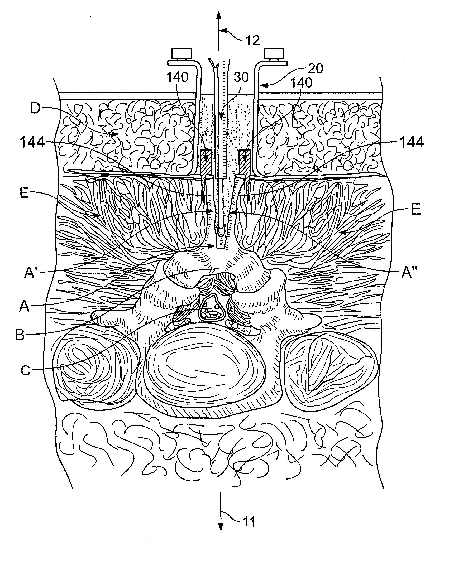
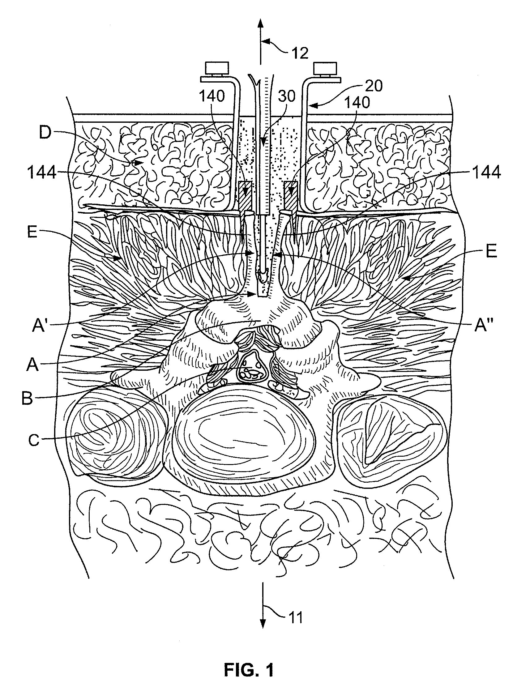
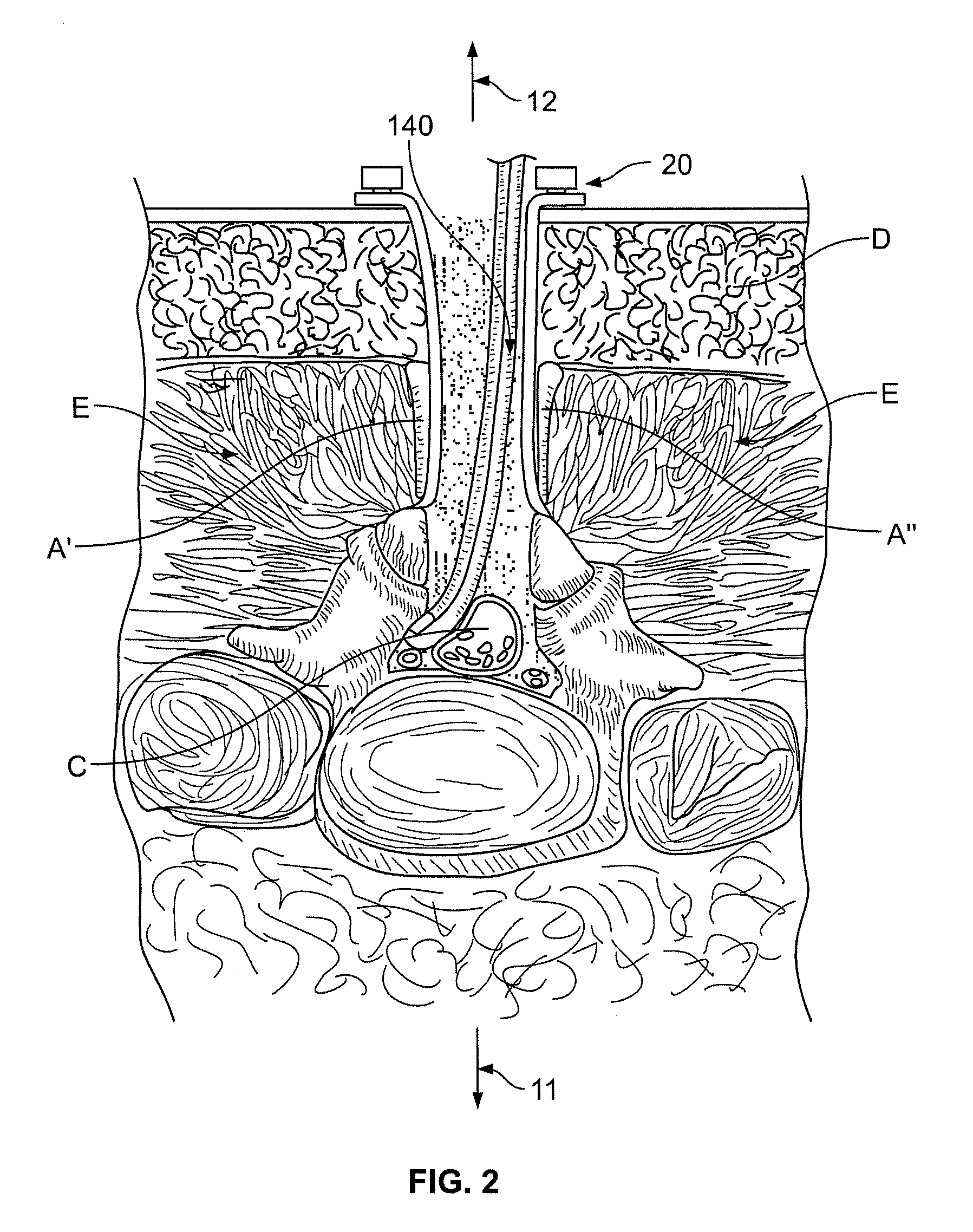
[0030] Although some embodiments of the invention described herein are directed to a method and system for performing a minimally-invasive spinal surgical procedure via a spinous process defining a posterior axis, it will be appreciated by one skilled in the art that the various embodiments of the invention are not so limited. For example, aspects of the cu...


PUM


Abstract

Various embodiments of the present invention provide, for example, a system and method for centering a surgical tool about the spinous process or other bony structure. Certain embodiments of the present invention may guide the surgical tool along a posterior midline of the spine in order to divide the spinous process. Various embodiments of the present invention may also further provide a system and method for performing a minimally invasive laminectomy procedure via the midline approach described above that may thus reduce the trauma experienced by tissues surrounding the spine or other bony structure.

Description

CROSS-REFERENCE TO RELATED APPLICATIONS [0001] This application claims priority to U.S. Provisional Patent Application No. 60 / 758,327, filed Jan. 12, 2006, which is hereby incorporated by reference herein in its entirety.FIELD OF INVENTION [0002] Various embodiments of the present invention relate to devices and methods for centering surgical cutting tools about a bony projection such as the spinous process. For example, some embodiments of the present invention may provide a centering method to better enable a minimally-invasive surgical procedure for splitting a spinous process at the dorsal midline of a subject in order to perform a spinal decompression procedure, such as laminectomy, for treating lumbar stenosis. BACKGROUND OF THE INVENTION [0003] A key issue in the safe and effective performance of minimally-invasive surgical procedures that involve the cutting of bone (particularly the cutting of cortical bone making up portions of the spinal column) is the protection of criti...

Claims


Application Information

Patent Timeline
Patent Type & Authority Applications(United States)
IPC IPC(8): A61F5/00
CPCA61B17/1757A61B17/1671
Inventor MACMILLAN, MICHAEL
Owner UNIV OF FLORIDA RES FOUNDATION INC
Why Eureka
Try Eureka