Steam generator

a generator and steam technology, applied in the direction of lighting and heating apparatus, container discharge methods, separation processes, etc., can solve the problems of heavy and bulky conventional steam generators for carpet cleaners, irons and the lik

Inactive Publication Date: 2010-09-21
TECHNICAL (HK) MANUFACTURING LIMITED
View PDF27 Cites 24 Cited by
  • Summary
  • Abstract
  • Description
  • Claims
  • Application Information

AI Technical Summary

Benefits of technology

[0009]In a preferred embodiment, the heating element forms part of a wall of the conduit. In this way water passes directly in contact with the heating element facilitating rapid heating and minimising thermal losses.
[0011]In a particularly preferred embodiment, the channel comprises an axial cylindrical portion which provides a socket for reception of the heating element. The cylindrical portion may be U-shaped, C-shaped or otherwise folded. The channel further comprises an outer passageway for water and / or steam around the socket. A continuous spiral or helical flange extends radially inwardly from the outer wall of the passageway, the flange having an axial bore or aperture to define the cylindrical portion. In this way the element is securely engaged by the spiral or helical surface of the flange along the length of the passageway.
[0014]In use of the apparatus water is forced to run through the helical coiled or folded path increasing the contact time between the water and heating element. This provides optimal efficiency of steam generation. The longer the water is in contact with the element, the more thermal energy is used to generate steam. Since the chamber is enclosed, pressure is developed. The higher steam pressure created results in a higher steam temperature.
[0015]In preferred embodiments the conduit comprises a labyrinthine passageway to maximise heating of the steam. One or more regions of restricted cross sectional area may be provided to restrict the flow of water or steam to enhance the pressure of steam generated.
[0020]A steam generator of the present invention is efficient and is advantageous in comparison to conventional big boiler type steam generators. Smaller boiler type steam generators may only generate small bursts of steam whereas apparatus in accordance with the present invention may provide a continuous supply of steam.

Problems solved by technology

Conventional steam generators for carpet cleaners, irons and the like are very bulky, heavy and include a boiler for boiling and maintaining a supply of heated water.

Method used


Image

  • Steam generator
  • Steam generator
  • Steam generator

Examples


Embodiment Construction

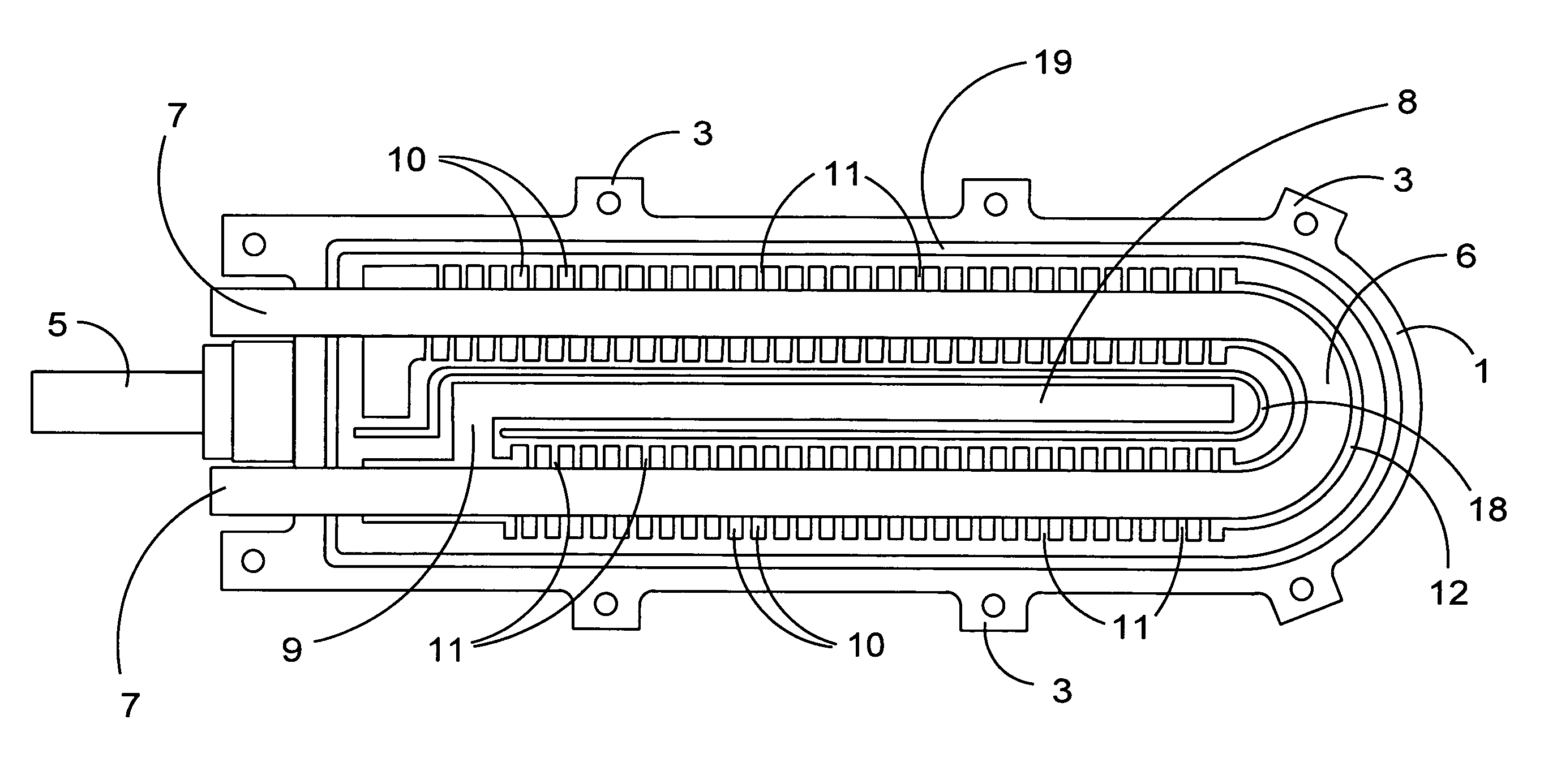
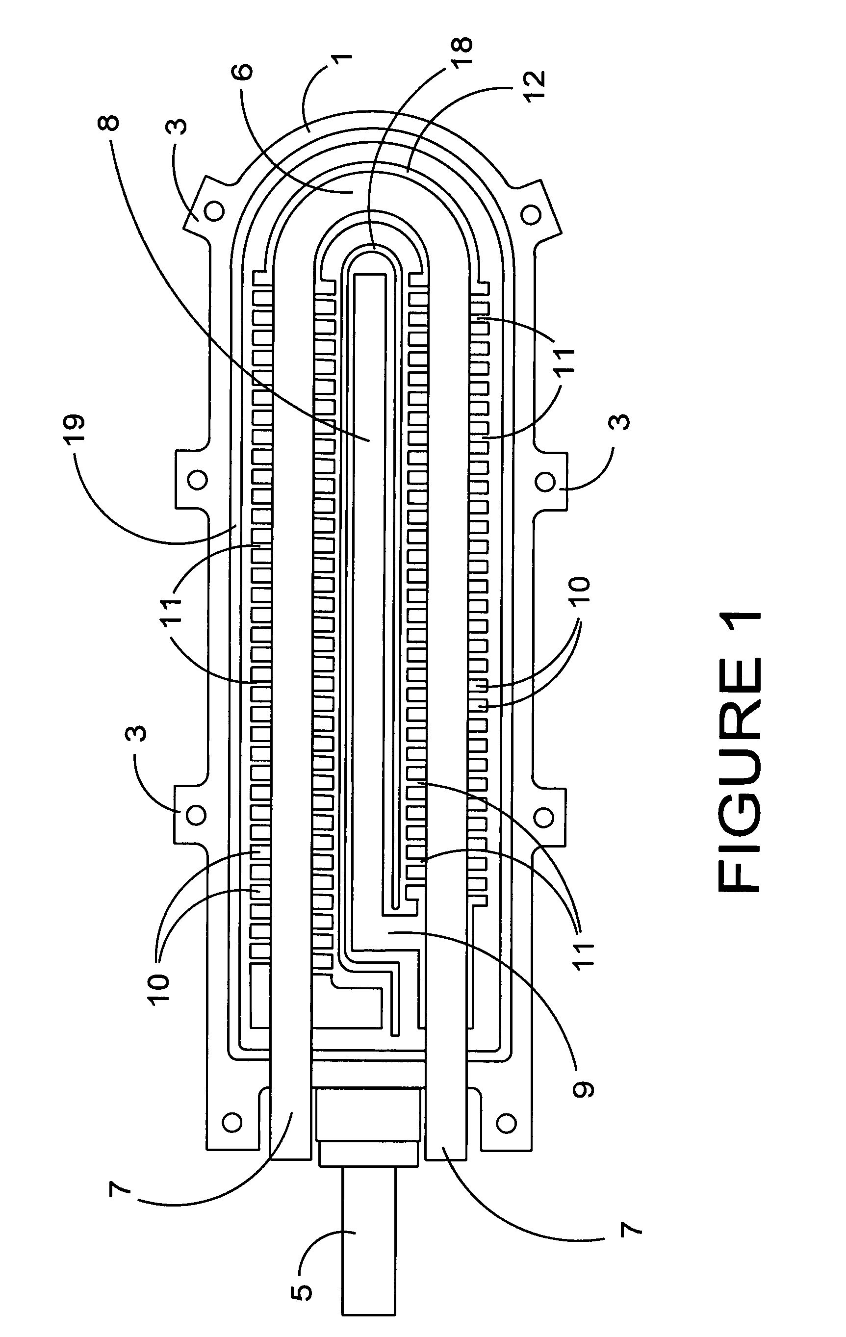
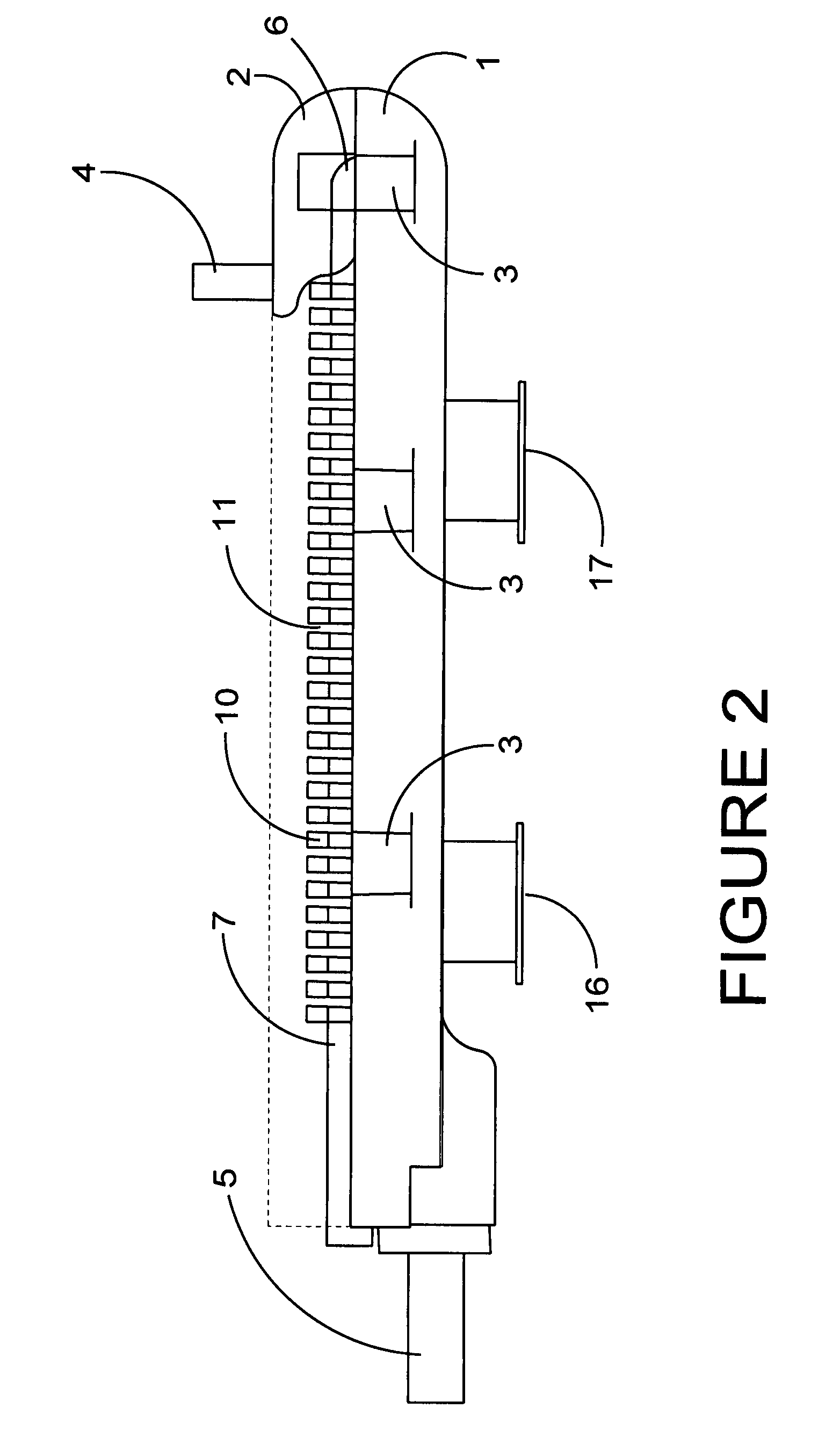
[0032]The steam generator shown in the drawings comprises a lower housing (1) adapted to be secured to an upper housing (2) by means of bolted flanges (3). The upper and lower housing portions (1, 2) may comprise zinc or other metallic castings and are most preferably elongate having an inlet (4) for water and an outlet (5) for steam. A U-shaped heating element (6) having two parallel limbs (7) is received in a complementary dimensioned channel located between engaging surfaces of the housing half portions (1, 2). The conduit comprises a preheat section (8) extending from the inlet (4) lengthwise of the housing to an elbow portion (9) contacting one end of the element (6). The conduit extends along the limb (7) of the element (6) to define a chamber (10) along which water and steam may pass. A multiplicity of rib shaped flange plates (11) formed in each housing portion (1, 2) extend inwardly from the housing shell to contact the heating element limb (7). The flange plates (11) are d...


PUM


Abstract

A steam generator comprising a heating unit, a pump adapted to deliver a controllable flow of water from a water supply into the heating unit and an outlet for steam from the heating unit; the heating unit comprises a housing, a heating element disposed in the housing and a conduit for water and steam extending from the inlet to the outlet; the conduit includes a passageway extending in an elongate path in contact with or adjacent the heating element; wherein the housing comprises two portions releasably seamed together to provide a channel between the portions to receive the heating element and to provide the passageway.

Description

BACKGROUND OF THE INVENTION[0001]This invention relates to a steam generator particularly but not exclusively of the kind incorporated into hand held or portable apparatus for domestic or commercial uses, for example for cleaning or steaming carpets or textile articles. The steam generator may be used in carpet cleaners, clothes presses and irons, dental or jewellery cleaning equipment and for culinary or domestic sterilizers.[0002]Conventional steam generators for carpet cleaners, irons and the like are very bulky, heavy and include a boiler for boiling and maintaining a supply of heated water. This means that energy is expended in heating a large volume of water prior to use and in maintaining the water at elevated temperature.SUMMARY OF THE INVENTION[0003]According to the present invention, a steam generator comprising a heating unit, pump adapted to deliver a controllable flow of water from a water supply into the heating unit and an outlet for steam from the heating unit; the h...

Claims


Application Information

Patent Timeline
Patent Type & Authority Patents(United States)
IPC IPC(8): B01D3/06
CPCA61H33/063F22B1/282F22B1/288F22B27/14
Inventor CHEUNG, CHUN MING
Owner TECHNICAL (HK) MANUFACTURING LIMITED
Why Eureka
Try Eureka