Mechanical pencil

a mechanical pencil and pencil body technology, applied in the field of mechanical pencils, can solve the problems of difficult to observe the rotation of the cap, difficult to increase the writing efficiency, and not particularly arranged, and achieve the effect of preventing local abrasion of the writing lead and facilitating quality judgmen

Active Publication Date: 2010-09-28
MITSUBISHI PENCIL CO LTD
View PDF18 Cites 16 Cited by
  • Summary
  • Abstract
  • Description
  • Claims
  • Application Information

AI Technical Summary

Benefits of technology

[0020]According to the above-described mechanical pencil in accordance with the present invention, with application of the writing pressure, the rotor moves in the axial direction so that the first cam face of the rotor is brought to mesh with the first fixed cam face, and is subjected to rotational motion. Further, as the writing pressure is released, the rotor returns to the original position, and then operates so as to bring the second cam face of the rotor to mesh with the second fixed cam face so as to be subjected to the rotational motion in the same direction as in the above description. As the rotational motion of the above-mentioned rotor by way of the writing pressure is transmitted to the writing lead through the chuck, it is possible to prevent the local abrasion of the writing lead according to the progress of the writing and to solve the problem that the thickness of a drawn line and the boldness of the drawn line may change badly.
[0021]In addition, the indicator is provided for a part of the component accommodated in the body cylinder which is rotationally driven interlocking with the above-mentioned rotor or rotation of the rotor, and the above-mentioned indicator can be observed through the above-mentioned body cylinder made of a transparent material, whereby rotational drive behavior of the rotor (writing lead) can be observed as the above-mentioned indicator rotates and moves when writing. In use, this structure may cause a user to have interests or a pleasure somewhat, and it also appeals considerable product differentiation. Further, in operation inspection at the time of manufacturing and assembling the mechanical pencil, it is also possible to ease quality judgment by viewing.
[0022]Further, according to the mechanical pencil in accordance with the present invention, since a drive portion for rotating it, except for the writing lead, can be arranged to be accommodated in the body cylinder, it is possible to solve the above-mentioned problem in the structure of the mechanical pencil where the knock cap and the base are rotated interlocking with the rotational drive mechanism, as described in patent documents 1 to 3.

Problems solved by technology

According to the above-mentioned mechanical pencil, when rotating the rotor, there is a problem in that the writing lead needs to have a large enough retreat stroke to allow the projection on the rotor side to pass over the vertical projection formed in the body cylinder.
For this reason, special operation of rotating the writing lead in the middle of writing is required, and it is difficult to increase writing efficiency.
Further, when rotationally operating the writing lead, it is not particularly arranged to know whether the above-mentioned rotor is surely rotationally operated.
However, since the above-mentioned knock cap is formed in the shape of a simple cylinder, it is not easy to observe the cap rotating.
Rather, when the above-mentioned knock cap is arranged to be rotated interlocking with it, there arises a problem that the knock cap may be, for example, unintentionally rotated to damage the rotational drive mechanism.
In the structure described in this patent document 3, since the base is formed in the shape of a simple cone, it is not easy to check its rotation operation.
Rather, when the above-mentioned base rotates, there arises a problem that the base is gripped etc., when writing so as to inhibit the rotation operation.
Therefore, there is no way of thinking of positively knowing the rotation operation either in the mechanical pencil described in patent document 3 above.

Method used


Image

  • Mechanical pencil
  • Mechanical pencil
  • Mechanical pencil

Examples


Embodiment Construction

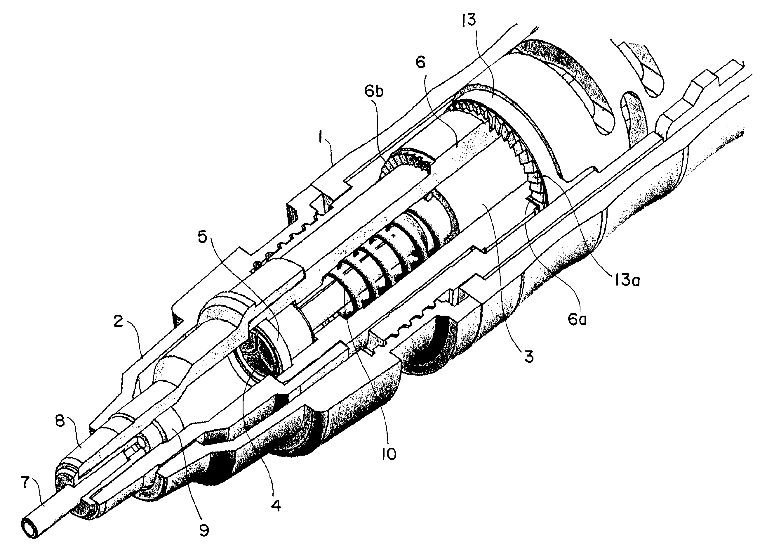
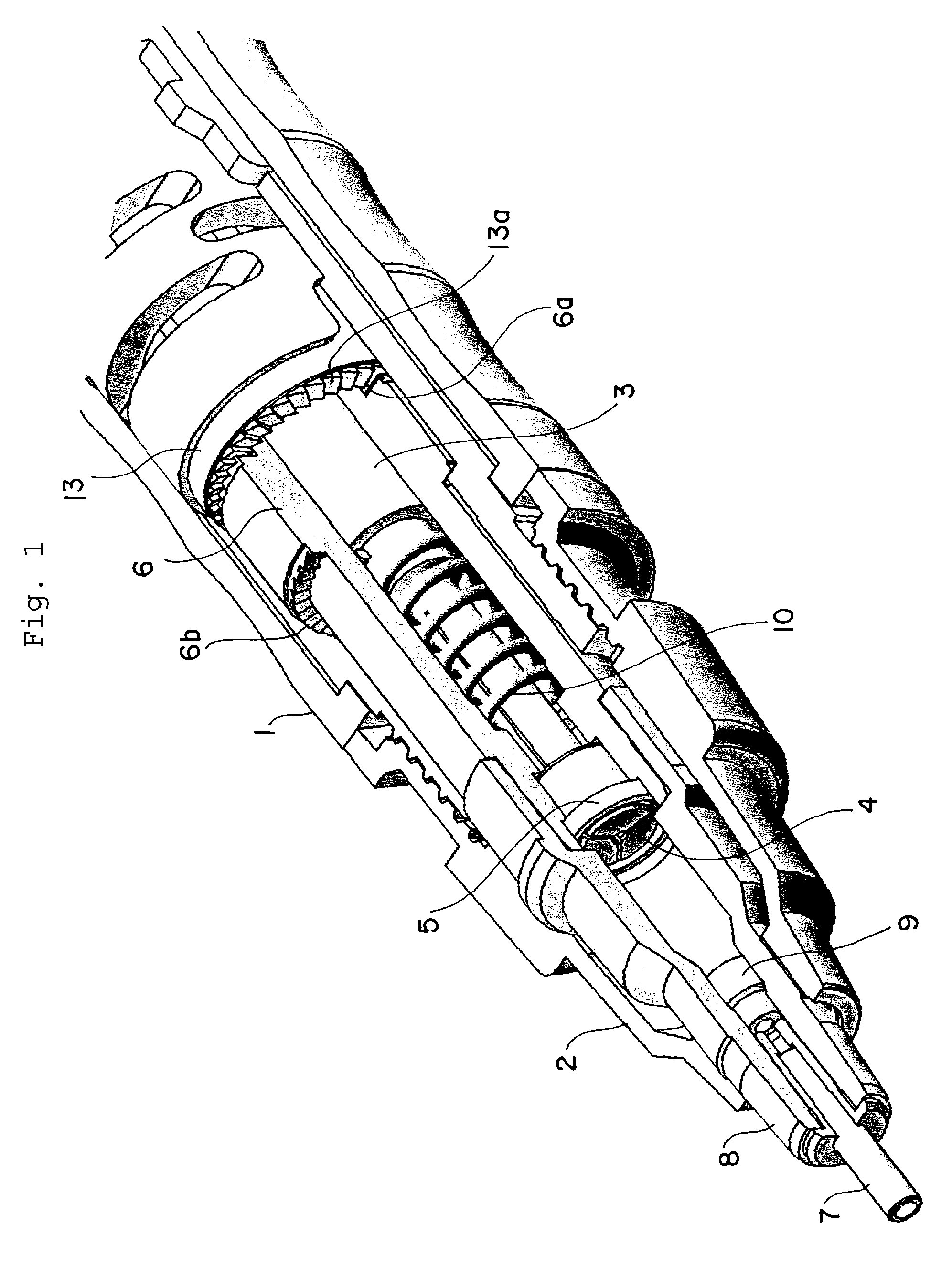
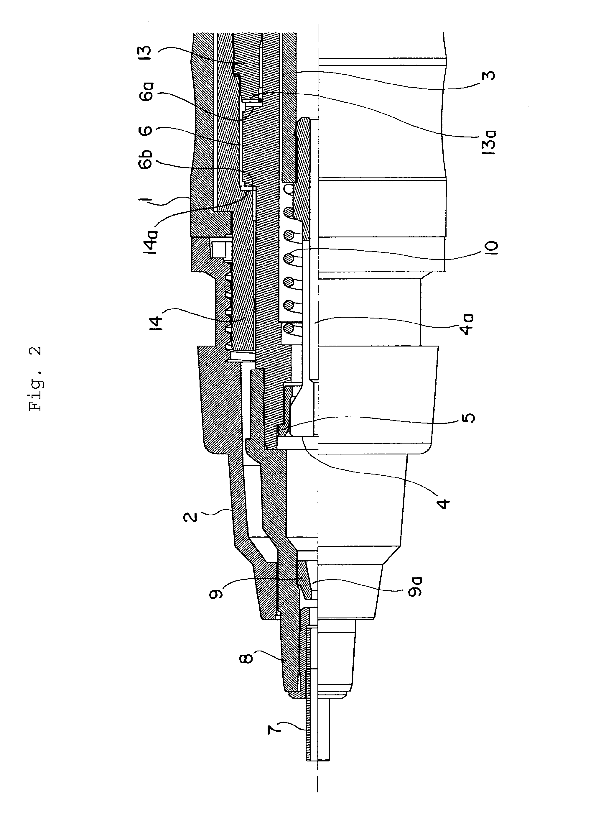
[0059]Hereinafter, a mechanical pencil in accordance with the present invention will be described with reference to the embodiments illustrated in the drawings. FIGS. 1 and 2 show a first half part of the mechanical pencil which is a principal part of the present invention. FIG. 1 is a perspective view showing its principal part, partially broken-away, and FIG. 2 is a side elevation where a left half portion is shown in section.

[0060]Reference numeral 1 denotes a body cylinder which constitutes the exterior, and reference numeral 2 indicates a base attached to a tip portion of the above-mentioned body cylinder 1. A cylindrical lead case 3 is accommodated coaxially in the center of the above-mentioned body cylinder 1, and a chuck 4 is connected with a tip portion of the lead case 3. The chuck 4 is mounted so that a through hole 4a is formed along an axis thereof, a tip portion is divided in three directions, and the divided tip portions are loosely fitted in a clamp 5 which is formed...


PUM


Abstract

A chuck (4) for grasping a writing lead and a rotor (6) arranged to be movable in a direction of rotation and an axial direction within a body cylinder (1). A rotational drive mechanism for the writing lead is formed such that first and second cam faces (6a) and (6b) are respectively formed at one end face and another end face of the rotor in the axial direction, and first and second fixed cam faces (13a) and (14a) are arranged on the body cylinder side to face the above-mentioned first and second cam faces respectively. An indicator (6c) of a wedge-shaped notch is formed at a part of the rotor. The indicator can be observed through the body cylinder made of a transparent material. By this structure, a mechanical pencil is provided in which operation of the writing lead that is gradually rotated by way of writing pressure can be known certainly.

Description

TECHNICAL FIELD[0001]The present invention relates to a mechanical pencil which can rotate a writing lead (refill lead) by writing pressure.BACKGROUND ART[0002]In the case of writing with a mechanical pencil, it is generally often the case that the mechanical pencil is not used in a situation where a body cylinder is perpendicular to a writing side (page), but used in a situation where the body cylinder is somewhat inclined to the writing side. In the case where the body cylinder is thus inclined for writing, there arises a phenomenon that a drawn line becomes bold as compared with that in the beginning, since the writing lead may locally abrade as the writing proceeds. Further, not only the drawn line changes in boldness, but also there arises a phenomenon that the drawn line changes in thickness (drawn line becomes thin) as the writing proceeds, since a contact area of the writing lead changes with respect to the writing side.[0003]In order to avoid the above-mentioned problem, wh...

Claims


Application Information

Patent Timeline
Patent Type & Authority Patents(United States)
IPC IPC(8): B43K21/22B43K5/12
CPCB43K21/003B43K21/006B43K21/027B43K29/08B43K21/22B43K29/02B43K21/16
Inventor IZAWA, HIROTAKEKOBAYASHI, TAKESHINAKAYAMA, KYO
Owner MITSUBISHI PENCIL CO LTD
Why Eureka
Try Eureka